fbcp ili9341
1.0.0
Die Ära von FBCP-ILI9341 ist zu Ende gegangen. FBCP-ILI9341 wurde auf der Videokore-API von Raspberry Pi aufgebaut.
Diese API wird jedoch seit einiger Zeit von der Raspberry Pi Foundation veraltet und schließlich auf Raspberry Pi 5 und weiter veraltet (= nicht verfügbar).
Die spätere Raspberry PI-Distribos haben nicht mehr dispmanx aktiv für pi0-pi4 aktiv, sondern Raspberry Pi hat sich auf den neueren KMS-Treiberkompositor-Stack übergeben, der eine andere Abstraktion für die Integration von SPI-Display-Treibern aufweist. Andere Menschen entwickeln SPI -Display -Treiber für den PI, die mit dem KMS -Stapel kompatibel sind. Gehen Sie zu diesem Raspberry Pi Forum -Thread, um mehr zu erfahren.
Dieses Repository ist gut, als archiviert/abgestanden zu sein, obwohl ich es nicht mit der Github-Funktion markiere, da diese Funktion den Ausgabe-Tracker offenbar auch schreibgeschützt machen würde. Fühlen Sie sich frei, weiterhin Probleme im Tracker zu diskutieren.
Dieses Repository implementiert einen Treiber für bestimmte SPI-basierte LCD-Anzeigen für Raspberry Pi A, B, 2, 3, 4 und Null.

Die Arbeit wurde durch Neugier motiviert, nachdem sie diese Serie von Videos auf dem Retromancave YouTube -Kanal gesehen hatte:
In diesen Videos wird der SPI (GPIO) -Bus als Engpass bezeichnet. Die SPI -basierte Aktualisierung über einen seriellen Datenbus zeigt ein Bit pro Taktzyklus im Bus. Ein 320x240x16BPP -Display erfordert daher eine SPI -BUS -Taktrate von 73,728 MHz, um eine vollständige Aktualisierungsfrequenz von 60 fps zu erreichen. Nicht viele SPI-LCD-Controller können in der Praxis so schnell kommunizieren, sind jedoch auf eine 16-50-MHz-SPI-Busaktuhrengeschwindigkeit beschränkt, wodurch die maximale Aktualisierungsrate erheblich begrenzt wird. Können wir etwas dagegen tun?
Das FBCP-ILI9341-Projekt startete als Display-Treiber für das Adafruit 2,8 "320x240 TFT W/ Touchs-Bildschirm für Raspberry PI-Display, das den ILI9341-Controller verwendet. Zu diesem Display kann FBCP-ILI9341 eine 60FPS-Aktualisierungsrate erzielen, abhängig von dem Inhalt, abhängig davon, abhängig von dem Inhalt, abhängig davon, abhängig von den Inhalten das wird angezeigt.
Wie kommt es, dass FBCP-ILI9341 in der Bandbreite so eingeschränkt werden kann, dass FBCP-ILI9341 mit bis zu 60 fps aktualisiert zu können? Die Art und Weise, wie dies erreicht wird, beruht auf dem, was als adaptive Anzeige -Stream -Updates bezeichnet werden könnte. Anstatt jedes Pixel an jedem Anzeige -Refresh -Zyklus hochzuladen, werden nur die tatsächlich geänderten Pixel auf dem Bildschirm an die Anzeige übermittelt. Dies ist machbar, da der ILI9341 -Controller, wie viele andere beliebte Controller, über Kommunikationsschnittstellenfunktionen verfügen, die es ermöglichen, teilweise Bildschirmaktualisierungen bis hin zu Subaktivierungen oder sogar einzelner Pixelebenen anzugeben. Dies ermöglicht das Schlagen der Bandbreitengrenze: Zum Beispiel in Quake, obwohl es sich um ein schnelles Tempo -Spiel handelt, und im Durchschnitt nur etwa 46% aller Pixel auf dem Bildschirm ändern jeden gerenderten Rahmen. Einige Teile, wie die Benutzeroberfläche, bleiben über mehrere Rahmen hinweg praktisch konstant.
Andere Optimierungen werden ebenfalls verwendet, um noch mehr Leistung auszudrücken:
#define NO_INTERLACING in config.h in der Datei kontrollieren.Das Ergebnis ist, dass der SPI-Bus nahezu 100% gesättigt werden kann, ~ 94-97% üblich, um die Nutzungsrate des Busses zu maximieren, während nur praktisch die Mindestanzahl von Bytes übertragen wird, die zur Beschreibung jedes neuen Rahmens erforderlich sind.
Der Fahrer wurde auf die Arbeit überprüft (zumindest in der Vergangenheit) in den folgenden Systemen:
Obwohl nicht alle Boards aktiv getestet werden, sind YMMV insbesondere auf älteren Boards. (Bug -Fixes Willkommen, verwenden Sie https://elinux.org/rpi_hardwareHistory, um zu identifizieren, auf welchem Board Sie ausführen.
Die folgenden LCD -Anzeigen wurden getestet:
Überprüfen Sie die folgenden Abschnitte, um den Treiber einzurichten.
Dieser Treiber nutzt den Notro/FBTFT -Framebuffer -Treiber nicht, sodass deaktiviert werden muss, wenn sie aktiv sind. Das heißt, wenn Ihre Datei /boot/config.txt -Datei Zeilen enthält, die so etwas wie dtoverlay=pitft28r, ... , dtoverlay=waveshare32b, ... oder dtoverlay=flexfb, ... , sollten entfernt werden.
Dieses Programm verwendet weder den Standard -SPI -Treiber, daher sollte auch eine Zeile wie dtparam=spi=on in /boot/config.txt entfernt werden, damit es keine Konflikte verursacht.
penirq= Sie dtoverlay=ads7846,... aktiv sind, wie z. Es wäre möglich, FBCP-ILI9341 Berührungsunterstützung hinzuzufügen, wenn jemand einen Stich darüber machen möchte.
Laufen Sie in der Konsole Ihres Raspberry Pi:
sudo apt-get install cmake
cd ~
git clone https://github.com/juj/fbcp-ili9341.git
cd fbcp-ili9341
mkdir build
cd build
cmake [options] ..
make -j
sudo ./fbcp-ili9341
Beachten Sie insbesondere die beiden Punkte .. Auf der CMake -Linie, die in diesem Fall "ein Verzeichnis" bezeichnen (anstatt sich auf "Weitere Elemente hier zu beziehen").
Siehe den nächsten Abschnitt, um zu sehen, was unter [Optionen] eingegeben werden soll.
Wenn Sie den vorhandenen fbcp -Treiber ausgeführt haben, entfernen Sie diese EG zuerst über einen sudo pkill fbcp (während Sie in SSH -Eingabeaufforderung ausgeführt oder an ein HDMI -Display angeschlossen sind), aber diese beiden können nicht gleichzeitig ausgeführt werden. Wenn /etc/rc.local oder /etc/init.d einen Eintrag zum Start von fbcp am Boot enthält, sollte diese Anweisung gelöscht werden.
Es gibt im Allgemeinen zwei Möglichkeiten, Build -Optionen, in der CMAKE -Befehlszeile und in der Dateikonfiguration zu konfigurieren.
In der CMAKE -Befehlszeile können die folgenden Optionen konfiguriert werden:
Wenn Sie eine der Anzeigen verwenden, die auf dem PI stapelt, das bereits von FBCP-ILI9341 erkannt wird, müssen Sie die GPIO-PIN-Zuordnungen nicht angeben, aber FBCP-ILI9341-Code hat bereits diese. Geben Sie eine der folgenden CMake -Richtlinien für die Hüte bestehen:
-DADAFRUIT_ILI9341_PITFT=ON : Wenn Sie auf dem Adafruit 2.8 "320x240 TFT mit Touchscreen für Raspberry PI (oder das Adafruit Pitft 2,2" Hut Mini -Kit - 320x240 2.2 "TFT - Kein Touch -Display, vergleichbar) Flagge.-DADAFRUIT_HX8357D_PITFT=ON : Wenn Sie die Adafruit -Pitft haben - montiert 480 x 320 3,5 "TFT+Touchscreen für Raspberry Pi -Anzeige, fügen Sie diese Zeile hinzu.-DFREEPLAYTECH_WAVESHARE32B=ON : Wenn Sie auf dem Freeplay CM3 oder Null -Gerät laufen, übergeben Sie dieses Flag. (Dies ist kein Hut, aber immer noch eine vorkonfigurierte Pinzuordnung)-DWAVESHARE35B_ILI9486=ON : Wenn angegeben, zielt eine Waveshare 3,5 "480x320 ILI9486 Display ab.-DTONTEC_MZ61581=ON : Wenn Sie auf der TONTEC 3.5 "320x480 LCD -Anzeige ausführen, übergeben Sie dies.-DPIRATE_AUDIO_ST7789_HAT=ON : Wenn angegeben, zielt ein Pirate -Audio 240x240, 1,3 -Zoll -IPS -LCD -Anzeigehut für Raspberry Pi mit ST7789 Display -Controller ab-DWAVESHARE_ST7789VW_HAT=ON : Wenn angegeben, zielt ein 240x240, 1,3 -Zoll -IPS -LCD -Display -Hut für Raspberry Pi mit ST7789VW -Anzeigecontroller ab.-DWAVESHARE_ST7735S_HAT=ON : Wenn angegeben, zielt ein 128x128, 1,44 -Zoll -LCD -Display -Hut für Raspberry Pi mit ST7735S -Anzeigecontroller ab.-DKEDEI_V63_MPI3501=ON : Wenn angegeben, zielt ein Kedei 3,5 -Zoll -SPI TFTLCD 480*320 16bit/18bit Version 6.3 2018/4/9 Display mit MPI3501 Display Controller. Wenn Sie Drähte direkt auf dem PI angeschlossen haben, anstatt einen Hut aus der obigen Liste zu verwenden, müssen Sie die folgenden Konfigurationsanweisungen verwenden. Neben der Angabe des Displays müssen Sie FBCP-ILI9341 auch mitteilen, mit welchen GPIO-Stiften Sie die Verbindungen verkabelt haben. Um den Anzeigecontroller zu konfigurieren, übergeben Sie einen von:
-DILI9341=ON : Wenn Sie auf einem anderen generischen ILI9341 -Display oder auf Waveshare32B -Display, das eigenständig ist, und nicht auf dem Freeplaytech CM3/Zero -Gerät, bestehen dieses Flag.-DILI9340=ON : Wenn Sie eine ILI9340 -Anzeige haben, bestehen Sie diese Anweisung. ILI9340 und ILI9341 -Chipsätze sind sehr ähnlich, aber ILI9340 unterstützt nicht alle Funktionen auf ILI9341 und sie werden deaktiviert oder herabgestuft.-DHX8357D=ON : Wenn Sie ein HX8357D -Display haben, übergeben Sie diese Anweisung.-DSSD1351=ON : Wenn Sie eine SSD1351 -OLED -Anzeige haben, verwenden Sie dies.-DST7735R=ON : Wenn Sie eine ST7735R -Anzeige haben, verwenden Sie dies.-DST7789=ON : Wenn Sie ein ST7789 -Display haben, verwenden Sie dies.-DST7789VW=ON : Wenn Sie eine ST7789VW -Anzeige haben, verwenden Sie dies.-DST7735S=ON : Wenn Sie ein ST7735S -Display haben, verwenden Sie dies.-DILI9486=ON : Wenn Sie eine ILI9486 -Anzeige haben, bestehen Sie diese Anweisung.-DILI9486L=ON : Wenn Sie eine ILI9486L -Anzeige haben, bestehen Sie diese Anweisung. Beachten Sie, dass ILI9486 und ILI9486L sehr unterschiedliche, gegenseitig inkompatible Controller -Chips sind. Seien Sie also vorsichtig, um zu ermitteln, welche Sie haben. (oder versuchen Sie es einfach beides, sollten nicht brechen, wenn Sie falsch identifiziert haben)-DILI9488=ON : Wenn Sie eine ILI9488 -Anzeige haben, bestehen Sie diese Anweisung.-DMPI3501=ON : Wenn angegeben, zielt ein Display mit MPI3501 -Anzeigecontroller ab.Und geben Sie außerdem Folgendes weiter, um die von Ihnen verwendeten GPIO -PIN -Zuordnungen anzupassen:
-DGPIO_TFT_DATA_CONTROL=number : Gibt an, welchen GPIO-PIN für die Daten-/Steuerung (DC) für die 4-Draht-SPI-Kommunikation verwendet werden soll. Diese Pin -Nummer ist in BCM -PIN -Nummern angegeben. Wenn Sie eine 3-Wire-SPI-Anzeige haben, die keine Daten-/Kontrolllinie -DGPIO_TFT_DATA_CONTROL=-1 , setzen Kommunikation.-DGPIO_TFT_RESET_PIN=number : Gibt an, welche GPIO -PIN für die Anzeigereset -Zeile verwendet werden soll. Diese Pin -Nummer ist in BCM -PIN -Nummern angegeben. Wenn es weggelassen wird, wird angenommen, dass das Display keinen Reset -Stift hat und immer eingeschaltet ist.-DGPIO_TFT_BACKLIGHT=number : Gibt an, welche GPIO -PIN für die Backlight -Zeile Anzeige verwendet werden soll. Diese Pin -Nummer ist in BCM -PIN -Nummern angegeben. Wenn es weggelassen wird, wird davon ausgegangen, dass das Display keinen GPIO-kontrollierten Hintergrundbeleuchtungsstift hat und immer eingeschaltet ist. Wenn Sie dies festlegen, finden Sie auch die Option #define BACKLIGHT_CONTROL in config.h .FBCP-ILI9341 verwendet immer den Hardware SPI0-Anschluss, sodass die Miso-, MOSI-, CLK- und CE0-Stifte immer gleich sind und nicht geändert werden können. Der Miso -Pin wird tatsächlich nicht verwendet (momentan momentan), sodass Sie einfach überspringen können, um diese zu verbinden. Wenn es sich bei Ihrem Display um eine Schurke handelt, die die Chip -Enable -Linie ignoriert, können Sie diese auch das Verbinden weglassen oder möglicherweise auch in der Lage sein, diese mit dem Masse zu verbinden, wenn Sie die Verkabelung zu vereinfachen (je nach Display).
Um eine gute Leistung aus den Displays herauszuholen, werden Sie die Anzeigen weit über den Nenndrehzahlspezifikationen entfernt (die Nennspezifikationen ergeben je nach Anzeige etwa ~ 10 fps). Aus diesem Grund müssen Sie die Zielgeschwindigkeit, bei der Sie das Display fahren möchten, explizit konfigurieren, da aufgrund der Herstellungsvarianzen jede Displaykopie eine andere maximale Geschwindigkeit erreicht. Es gibt keine "Standardgeschwindigkeit", die FBCP-ILI9341 verwenden würde. Das Einstellen der Geschwindigkeit erfolgt über die Option
-DSPI_BUS_CLOCK_DIVISOR=even_number : Legt die Takt -Divisor -Nummer fest, die zusammen mit der Option pi core_freq = in /boot/config.txt die Gesamtgeschwindigkeit angibt, bei der der SPI -Kommunikationsbus der Anzeige gefahren wird. SPI_frequency = core_freq/divisor . SPI_BUS_CLOCK_DIVISOR muss eine gleichmäßige Zahl sein. Standard PI 3B und Null W core_freq beträgt 400 MHz, und im Allgemeinen scheint ein Wert -DSPI_BUS_CLOCK_DIVISOR=6 das Beste zu sein, was eine ILI9341 -Anzeige tun kann. Versuchen Sie einen größeren Wert, wenn das Display beschädigte Ausgabe oder einen kleineren Wert anzeigt, um eine höhere Bandbreite zu erhalten. Siehe ILI9341.H und Waveshare35B.H für Datenpunkte zum Stimmen der maximalen SPI -Leistung. Der sichere Anfangswert könnte so etwas wie -DSPI_BUS_CLOCK_DIVISOR=30 sein. Es gibt einige Optionen, um ausdrücklich mitzuteilen, welches PI -Board Sie ansprechen möchten. Diese sollten für Sie autodetiert werden und werden im Allgemeinen nicht benötigt, z. B. wenn Sie für ein anderes PI -Board aus einem anderen System zusammenstellen oder explizit sein möchten, können Sie versuchen:
-DSINGLE_CORE_BOARD=ON : Übergeben Sie diese Option, wenn Sie auf einem PI mit nur einem Hardware -Thread ausführen (PI -Modell A, PI -Modell B, Rechenmodul 1, Pi Zero/Null W). Wenn nicht vorhanden, autodetiert.-DARMV6Z=ON : Übergeben Sie diese Option, um den Befehlssatz von ARMV6Z spezifisch zu optimieren (PI 1A, 1A+, 1B, 1B+, Null, Null W). Wenn nicht vorhanden, autodetiert.-DARMV7A=ON : Übergeben Sie diese Option, um den Befehlssatz von ARMV7-A speziell zu optimieren (PI 2B <Rev. 1.2). Wenn nicht vorhanden, autodetiert.-DARMV8A=ON : Übergeben Sie diese Option, um den Befehlssatz von ARMV8-A speziell zu optimieren (PI 2B> = Rev. 1,2, 3B, 3B+, CM3, CM3 Lite, 4B, CM4, PI400). Wenn nicht vorhanden, autodetiert. Die folgenden Build -Optionen sind allgemein für alle Displays und PI -Boards geeignet. Sie passen den Build weiter an:
-DBACKLIGHT_CONTROL=ON : Wenn gesetzt, ermöglicht es FBCP-ILI9341, die Anzeige-Hintergrundbeleuchtung in der angegebenen Hintergrundbeleuchtung zu steuern. Das Display wird nach einer Zeit der Inaktivität auf dem Bildschirm eingeschlafen. Wenn nicht, wird die Hintergrundbeleuchtung nicht berührt.-DDISPLAY_CROPPED_INSTEAD_OF_SCALING=ON : Wenn gesetzt und der Quellvideo größer als die SPI -Anzeige -Videoauflösung ist, wird das Quellvideo auf der SPI -Anzeige angezeigt, indem Teile davon in alle Richtungen geschnitten werden, anstatt zu fassen.-DDISPLAY_BREAK_ASPECT_RATIO_WHEN_SCALING=ON : Wenn Skalierung von Quellvideo zu SPI -Anzeige, wird die Skalierung standardmäßig folgendes Seitenverhältnis durchgeführt und nach Bedarf Buchstabenboxen/Pillarboxes hinzugefügt. Wenn dies festgelegt ist, wird die Dehnung des Seitenverhältnisses durchgeführt.-DSTATISTICS=number : Gibt die auf dem Bildschirm angezeigte Ebene der Overlay -Statistiken an. 0: Deaktiviert, 1: aktiviert, 2: aktiviert und werden auch das Bildrate -Intervalldiagramm angezeigt. Der Standardwert ist 1 (aktiviert).-DUSE_DMA_TRANSFERS=OFF : Wenn angegeben, deaktiviert, deaktiviert sie mit DMA -Transfers (auf große Kosten der verlorenen CPU -Verwendung). Übergeben Sie diese Richtlinie Wenn DMA einige Probleme gibt, z. B. als Fehlerbehebung, wenn etwas nicht richtig aussieht.-DDMA_TX_CHANNEL=<num> : Gibt die DMA -Kanalnummer an, die für SPI -Sendungsbefehle verwendet werden soll. Ändern Sie dies, wenn Sie einen DMA -Kanalkonflikt finden.-DDMA_RX_CHANNEL=<num> : Gibt die DMA -Kanalnummer an, die für SPI -Empfangsbefehle verwendet werden soll. Ändern Sie dies, wenn Sie einen DMA -Kanalkonflikt finden.-DDISPLAY_SWAP_BGR=ON : Wenn diese Option übergeben wird, werden rote und blaue Farbkanäle umgekehrt (RGB <--> BGR) Swap. Einige Anzeigen haben ein entgegengesetztes Subpixel -Layout des Farbpanels, für das der Display -Controller nicht automatisch berücksichtigt wird. Definieren Sie dies daher, wenn blau und rot durcheinander gebracht werden.-DDISPLAY_INVERT_COLORS=ON : Wenn diese Option übergeben wird, ist die Pixel -Farbwert -Interpretation umgekehrt (White = 0, Black = 31/63). Standard: schwarz = 0, weiß = 31/63. Übergeben Sie diese Option, wenn das Anzeigebild wie ein Farbnegat der tatsächlichen Farben aussieht.-DDISPLAY_ROTATE_180_DEGREES=ON : Wenn eingestellt wird, wird die Anzeige um 180 Grad gedreht. Dies wirkt sich nicht auf die HDMI -Ausgabe aus, sondern nur die SPI -Anzeigeausgabe.-DLOW_BATTERY_PIN=<num> : Gibt einen GPIO -Pin an, der befragt werden kann, um den Batteriezustand zu erhalten. Wenn dies eingestellt ist, wird standardmäßig ein Symbol mit niedrigem Akku angezeigt, wenn der Stift niedrig gezogen wird (siehe config.h , wie dies optimiert werden kann). Zusätzlich zu den oben genannten CMAKE -Direktiven gibt es verschiedene Definitionen, die um die Codebasis verteilt sind, hauptsächlich in config.h, die verschiedene Laufzeitoptionen steuern. Bearbeiten Sie diese direkt, um das Verhalten des Programms weiter in Einklang zu bringen. Insbesondere nach Abschluss des Setups möchten Sie möglicherweise mit -DSTATISTICS=0 Option in der CMake -Konfigurationsleitung erstellen.
Hier ist ein vollständiges Beispiel für das Erstellen und Ausführen, wenn Sie den Adafruit 2,8 "320x240 TFT mit Touchscreen für Raspberry Pi mit ILI9341 -Controller haben:
 cd ~
sudo apt-get install cmake
git clone https://github.com/juj/fbcp-ili9341.git
cd fbcp-ili9341
mkdir build
cd build
cmake -DSPI_BUS_CLOCK_DIVISOR=6 -DADAFRUIT_ILI9341_PITFT=ON ..
make -j
sudo ./fbcp-ili9341
Wenn das obige nicht funktioniert, versuchen Sie, -DSPI_BUS_CLOCK_DIVISOR=8 oder =10 anzugeben, damit das Display etwas langsamer ausgeführt wird, oder versuchen Sie es mit -DUSE_DMA_TRANSFERS=OFF , wenn DMA möglicherweise das Problem sein könnte. Wenn Sie einen anderen Display -Controller als ILI9341 verwenden, kann ein viel höherer Wert wie 30 oder 40 erforderlich sein. Wenn Sie die CMAKE -Optionen ändern, können Sie die CMake -Direktive -Linie wiedergeben, ohne das build -Verzeichnis wieder aufzunehmen oder neu erstellen zu müssen. Möglicherweise müssen Sie jedoch die Datei cmakecache.txt manuell löschen, zwischen den Optionen geändert, um zu vermeiden, dass CMAKE die alten Einstellungen erinnert.
Wenn Sie einen vollständigen Umbau von Grund auf neu machen möchten, können Sie rm -rf build um das Build -Verzeichnis zu löschen und es für einen sauberen Wiederaufbau von Grund auf neu zu erstellen. Der Name oder Ort dieses Verzeichnisses ist nichts Besonderes, es ist nur meine übliche Konvention. Sie können den Build auch in einem anderen Verzeichnis relativ zum FBCP-ILI9341-Verzeichnis durchführen, wenn Sie möchten.
Um den Treiber für den Start beim Start einzurichten, bearbeiten Sie die Datei /etc/rc.local im sudo -Modus und fügen Sie eine Zeile hinzu
sudo /path/to/fbcp-ili9341/build/fbcp-ili9341 & bis zum Ende. Notieren Sie sich die erforderlichen Ampersanden & am Ende dieser Linie.
Wenn Sie beispielsweise die oben aufgeführten Befehlszeilenschritte zum Erstellen verwendet haben, empfangen die Datei /etc/rc.local eine Zeile
sudo /home/pi/fbcp-ili9341/build/fbcp-ili9341 & Wenn der Benutzername Ihrer Raspberry PI -Installation etwas anderes als der Standard pi ist, ändern Sie das Verzeichnis entsprechend, um auf das Heimverzeichnis des Benutzers zu verweisen. (Verwenden Sie pwd , um das aktuelle Verzeichnis im Terminal herauszufinden)
systemd Verwenden Sie anstatt /etc/rc.local die bereitgestellte systemd -Einheitsdatei wie unten zu modifizieren: anstatt zu ändern:
sudo install -m 0644 -t /etc fbcp-ili9341.conf
sudo install -m 0644 -t /etc/systemd/system fbcp-ili9341.service
sudo systemctl daemon-reload
sudo systemctl enable fbcp && sudo systemctl start fbcp Wenn sich die Größe des Standard -HDMI -Ausgangs /dev/fb0 -Frambuffer von der Auflösung der Anzeige unterscheidet, wird die Quellvideogröße standardmäßig neu auf die Größe der SPI -Anzeige anpasst. FBCP-ILI9341 verwaltet die Einrichtung dieser Neuanlage bei Bedarf und erfolgt von der GPU, sodass die Leistung nicht zu stark beeinflusst werden sollte. Wenn die Auflösungen jedoch nicht übereinstimmen, erscheint ein kleiner Text wahrscheinlich unleserlich. Die Größenänderung erfolgt in der Verhältnisverhältnis. Wenn die Seitenverhältnisse nicht übereinstimmen, werden weder horizontale noch vertikale schwarze Grenzen auf dem Display angezeigt. Wenn Sie die HDMI -Ausgabe überhaupt nicht verwenden, ist es wahrscheinlich am besten, die HDMI -Ausgabe so zu konfigurieren, dass sie mit der SPI -Anzeigegröße entspricht, damit keine Neuschläge benötigt werden. Dies kann durchgeführt werden, indem die folgenden Zeilen in /boot/config.txt festgelegt werden:
 hdmi_group=2
hdmi_mode=87
hdmi_cvt=320 240 60 1 0 0 0
hdmi_force_hotplug=1
Wenn Ihr SPI -Display eine andere Auflösung hat als 320x240, ändern Sie den Teil 320 240 in ZB 480 320 .
Diese Zeilen deuten native Anwendungen zum Standardanzeigemodus an und lassen Sie sie auf die native Auflösung der TFT -Anzeige rendern. Dies kann jedoch die Verwendung des HDMI -Anschlusses verhindern, wenn die HDMI -angeschlossene Anzeige eine solche geringe Auflösung nicht unterstützt. Als Kompromiss können sowohl HDMI- als auch SPI -Displays gleichzeitig verwendet werden, eine andere kompatible Auflösung wie 640 x 480. In den verfügbaren Optionen finden Sie die verfügbaren Optionen für Raspberry Pi HDMI.
Die Aktualisierungsgeschwindigkeit des Displays wird durch die Taktgeschwindigkeit des SPI -Busses diktiert, mit dem das Display verbunden ist. Aufgrund der Art und Weise, wie der BCM2835 -Chip auf Raspberry Pi funktioniert, gibt es keine einfache speed=xxx Mhz -Option, die so eingestellt werden kann, dass die Busgeschwindigkeit definiert wird. Stattdessen wird die SPI -Busgeschwindigkeit aus zwei separaten Parametern abgeleitet: der Kernfrequenz des BCM2835 -SOC im Allgemeinen ( core_freq in /boot/config.txt ) und der SPI -Peripherie CDIV -Einstellung (Taktivider). Zusammen wird die resultierende SPI -Busgeschwindigkeit dann mit der Formel SPI_speed=core_freq/CDIV berechnet.
So optimieren Sie das Display so schnell wie möglich,
Passen Sie den CDIV -Wert an, indem Sie die Anweisung -DSPI_BUS_CLOCK_DIVISOR=number in der CMake -Befehlszeile übergeben. Mögliche Werte sind sogar Zahlen 2 , 4 , 6 , 8 , ... Beachten Sie, dass kleinere Werte, da CDIV im Nenner in der Formel für SPI_speed erscheint, zu höheren Busgeschwindigkeiten führen, während höhere Werte das Display langsamer machen. Wenn Sie zunächst nicht wissen, wie schnell Ihr Display ausgeführt werden kann, beginnen Sie mit einer sicheren hohen Einstellung wie -DSPI_BUS_CLOCK_DIVISOR=30 und arbeiten Sie zu kleineren Zahlen, um die maximale Geschwindigkeit zu finden, mit der das Display mithalten kann. In der Tabelle am Ende des ReadME finden Sie spezifische beobachtete maximale Busgeschwindigkeiten für verschiedene Anzeigen.
Gewährleistung der Geschwindigkeit von Turbo. Dies ist entscheidend für gute Bildraten. Auf dem Raspberry Pi 3 -Modell B läuft der BCM2835 -Kern standardmäßig bei 400 MHz (was zu 400/CDIV -MHz -SPI -Geschwindigkeit führt), wenn der PI genügend Leistung zur Verfügung steht und wenn die CPU -Temperatur die thermischen Grenzwerte nicht überschreitet. Wenn die CPU im Leerlauf oder die Spannung niedrig ist, kehrt der BCM2835-Kern stattdessen in den nicht-Turbo-250-MHz-Zustand zurück, was zu einer SPI-Geschwindigkeit von 250/CDIV MHz führt. Dieser Effekt der Turbo-Geschwindigkeit auf die Leistung ist signifikant, da 400 MHz gegenüber Nicht-Turbo-250 MHz auf +60% der mehr Bandbreite auftreten. Wenn Sie 60 FPS in Quake, Sonic oder Tyrian erhalten, benötigen diese Turbofrequenz häufig, aber z. Wenn aus irgendeinem Grund ein Unterspannungsschutz einnimmt, auch wenn genügend Strom gefüttert werden sollte, können Sie Turbo erzwingen, wenn eine niedrige Spannung vorhanden ist, indem der Wert avoid_warnings=2 in der Datei /boot/config.txt festgelegt wird.
Vielleicht ein bisschen kontinuterig, den Kern unterstreichen . Das Einstellen einer kleineren Kernfrequenz als der Standard -Turbo -400 -MHz kann die Verwendung eines kleineren Uhrenteilers aktivieren, um eine höhere resultierende SPI -Busgeschwindigkeit zu erhalten. Wenn beispielsweise mit Standard core_freq=400 SPI CDIV=8 funktioniert (was zu einer SPI -Busgeschwindigkeit 400MHz/8=50MHz führt), CDIV=6 jedoch nicht ( 400MHz/6=66.67MHz war zu viel), können Sie versuchen, core_freq=360 zu senken) core_freq=360 und setzen CDIV=6 um eine effektive SPI -Busgeschwindigkeit von 360MHz/6=60MHz zu erhalten, einen Mittelweg zwischen den beiden, der möglicherweise funktionieren könnte. Durch das Ausgleich von core_freq= und CDIV -Optionen können die maximale SPI -Busspeed bis zu den letzten KHz ermittelt werden, die der Display -Controller tolerieren kann. Man kann auch die entgegengesetzte Richtung und Übertaktung ausprobieren, aber das hat natürlich alle Probleme, die beim Übertakten kommen. Der Untertakt hat den Nachteil, dass der PI insgesamt langsamer läuft. Dies ist sicherlich ein Kompromiss.
Andererseits ist es wünschenswert zu steuern, wie viel CPU-Zeit FBCP-ILI9341 verwenden darf. Die Standard -Build -Einstellungen werden abgestimmt, um die Aktualisierungsrate der Anzeige auf Kosten des Stromverbrauchs auf PI 3B zu maximieren. Bei PI Zero ist das Gegenteil erledigt. Der Treiber optimiert standardmäßig für die Batteriesparen anstelle der maximalen Geschwindigkeit der Anzeige -Aktualisierung. Die folgenden Optionen können kontrolliert werden, um zwischen diesen beiden auszugleichen:
Die Hauptoption zur Steuerung der CPU -Nutzung im Vergleich zum Leistungs -Aspekt ist die Option #define ALL_TASKS_SHOULD_DMA in config.h . Durch die Aktivierung dieser Option wird die CPU -Verwendung erheblich reduziert. Wenn diese Option deaktiviert ist, wird die SPI-Busauslastung maximiert, die CPU-Verwendung kann jedoch bis zu 80%-120%betragen. Wenn diese Option aktiviert ist, beträgt die CPU-Nutzung im Allgemeinen bis zu 15%-30%. Die maximale CPU -Verwendung erfolgt beim Ansehen eines Videos oder beim Spielen eines sich schnell bewegenden Spiels. Wenn sich auf dem Bildschirm nichts ändert, sollte der CPU-Verbrauch des Fahrers sehr nahe bei 0 bis 5%sinken. Standardmäßig ist #define ALL_TASKS_SHOULD_DMA für PI Zero aktiviert, aber für PI 3B deaktiviert.
Die CMAKE -Option -DUSE_DMA_TRANSFERS=ON sollte immer für eine gute Niedrig -CPU -Verwendung aktiviert werden. Wenn DMA -Transfers deaktiviert sind, wird der Treiber im befragten SPI -Modus ausgeführt, der im Allgemeinen einen vollständigen Einzelkern der CPU -Zeit verwendet. Wenn DMA -Transfers Probleme verursachen, stellen Sie versuchen, die DMA -Send -Kanäle anzupassen und zu empfangen, um die SPI -Kommunikation mit -DDMA_TX_CHANNEL=<num> und -DDMA_RX_CHANNEL=<num> CMAKE -Optionen zu verwenden.
Die Statistiküberlagerung druckt recht detaillierte Informationen zum Ausführungszustand aus. Deaktivieren Sie die Überlagerung mit -DSTATISTICS=0 Option zur CMake verbessert die Leistung und reduziert die CPU -Verwendung. Wenn Sie weiterhin Statistiken drucken möchten, können Sie versuchen, das Intervall mit der Option #define STATISTICS_REFRESH_INTERVAL <timeInMicroseconds> in config.h zu erhöhen.
Aktivieren #define USE_GPU_VSYNC reduziert den CPU -Verbrauch, kann jedoch aufgrund von RaspberryPI/Userland #440 zu Stottern führen. Die Deaktivierung #defined USE_GPU_VSYNC erzeugt weniger Stottern, erhöht jedoch aufgrund von RaspberryPI/Userland #440 den CPU -Stromverbrauch.
Die Option #define SELF_SYNCHRONIZE_TO_GPU_VSYNC_PRODUCED_NEW_FRAMES kann in Verbindung mit #define USE_GPU_VSYNC verwendet werden, um zu versuchen, einen Mittelweg zwischen RaspberryPI/Userland #440 -Ausgaben zu finden - moderieren bis zu wenig Stottern, während sie nicht zu viel CPU konsumiert. Versuchen Sie, diese Einstellung zu aktivieren oder zu deaktivieren.
In config.h gibt es eine Reihe von #define SAVE_BATTERY_BY_x -Optionen, die alle Standardeinstellungen für aktiviert sind. Diese sollten ohne Kompromisse immer sicher sein. Wenn Sie Latenz- oder leistungsbezogene Probleme haben, können Sie versuchen, diese in die Fehlerbehebung umzuschalten.
Die Option #define DISPLAY_FLIP_ORIENTATION_IN_SOFTWARE verursacht ein bisschen zusätzliche CPU -Verwendung. Deaktivieren Sie daher das Laden der CPU ein wenig.
Wenn Ihr SPI -Displaybus im Vergleich zur Größe des Displays und der auf dem Bildschirm geänderten Inhaltsmenge sehr schnell ausgeführt werden kann, können Sie versuchen, #define UPDATE_FRAMES_IN_SINGLE_RECTANGULAR_DIFF in config.h zu aktivieren, um die CPU -Verwendung auf Kosten der Erhöhung zu reduzieren Die Anzahl der Bytes, die über den Bus gesendet wurden. Es wurde beobachtet, dass dies einen großen Einfluss auf Pi Zero hat, und es lohnt sich, insbesondere dort zu überprüfen.
Wenn der SPI -Displaybus in der Lage ist, wirklich sehr schnell auszuführen (oder Sie sich nicht um die Bildrate, aber nur die Nutzung der CPU -Nutzung des CPU) können Sie versuchen, #define UPDATE_FRAMES_WITHOUT_DIFFING in config.h zu aktivieren, um auf das adaptive Delta -Differing zu verzichten Option insgesamt. Dies wird zu naiven Vollbild -Updates für die absolut minimale Gesamtnutzung der CPU zurückgeführt.
Die Option #define RUN_WITH_REALTIME_THREAD_PRIORITY kann aktiviert werden, damit der Treiber bei Echtzeitprozess Priorität ausgeführt wird. Dies kann das System jedoch einsperren, aber dennoch für fortschrittliche Experimente zur Verfügung gestellt werden.
In display.h gibt es eine Option #define TARGET_FRAME_RATE <number> . Wenn Sie dies auf einen kleineren Wert wie 30 festlegen, handeln Sie die Refresh -Rate, um den CPU -Verbrauch zu senken.
Ein erfreulicher Aspekt von FBCP-ILI9341 ist, dass es nur sehr wenig Latenz-Overhead einführt: Auf einem 119-Hz-Aktualisierung von ILI9341 erhält FBCP-ILI9341 Pixel als Reaktion von GPIO-Eingaben, um in einer Zeit von weit weniger als 16,66 ms. Ich habe nur eine 120-fps-Aufzeichnungskamera. Daher kann es nicht leicht messen des ili9341.
Dies bedeutet nicht, dass die Gesamteingabe zur Anzeige der Latenz in Spielen so unmittelbar wäre. Ein kurzes Testen eines NES-emulierten Spiels in Retropie schlägt eine Gesamtlatenz von etwa 60 bis 80 ms vor. Diese Latenz wird durch den NES Game -Emulator -Overhead und die zusätzliche Latenz verursacht, die von Linux, Dispmanx und GPU -Rendering sowie GPU -Framebuffer -Snapshotting hinzugefügt wird. (Wenn Sie FBCP-ILI9341 als statische Bibliothek für Dispmanx und den GPU-Stack ausgeführt haben und Ihre GPIO-Eingabe- und Anwendungslogik direkt mit FBCP-ILI9341 verknüpfen, könnten Sie in der Lage sein, sich auf diese wenigen MSECs der Gesamtlatenz zu befassen, wie gezeigt in der In-the-Latenz, wie in der In-the-Latenz, wie in der Oben GPIO -Eingabevideo)
Interessanterweise ist FBCP-ILI9341 etwa ~ 33 msecs schneller als ein billiges 3,5-Zoll-Kedei-HDMI-Display. Ich weiß nicht, ob dies ein Ergebnis des Kedei-HDMI Latenzaufwand.
Leider ist eine Einschränkung von SPI -angeschlossenen Anzeigen, dass das VSYNC -Leitungssignal bei den Display -Controllern nicht verfügbar ist, wenn sie im SPI -Modus ausgeführt werden . Zum Beispiel können die 4 ILI9341-Displays, die ich habe, alle schneller als 75 MHz ausgeführt werden, sodass die SPI-Busbandbreite in Bezug vsync since the display controllers do not report it. (If you do know of a display that does actually expose a vsync clock signal even in SPI mode, you can try implementing support to locking on to it)
You can however choose between two distinct types of tearing artifacts: straight line tearing and diagonal tearing . Whichever looks better is a bit subjective, which is why both options exist. I prefer the straight line tearing artifact, it seems to be less intrusive than the diagonal tearing one. To toggle this, edit the option #define DISPLAY_FLIP_ORIENTATION_IN_SOFTWARE in config.h . When this option is enabled, fbcp-ili9341 produces straight line tearing, and consumes a tiny few % more CPU power. By default Pi 3B builds with straight line tearing, and Pi Zero with the faster diagonal tearing. Check out the video Latency and tearing test #2: GPIO input to display latency in fbcp-ili9341 and tearing modes to see in slow motion videos how these two tearing modes look like.
Another option that is known to affect how the tearing artifact looks like is the internal panel refresh rate. For ILI9341 displays this refresh rate can be adjusted in ili9341.h , and this can be set to range between ILI9341_FRAMERATE_61_HZ and ILI9341_FRAMERATE_119_HZ (default). Slower refresh rates produce less tearing, but have higher input-to-display latency, whereas higher refresh rates will result in the opposite. Again visually the resulting effect is a bit subjective.
To get tearing free updates, you should use a DPI display, or a good quality HDMI display. Beware that cheap small 3.5" HDMI displays such as KeDei do also tear - that is, even if they are controlled via HDMI, they don't actually seem to implement VSYNC timed internal operation.
Having no vsync is not all bad though, since with the lack of vsync, SPI displays have the opportunity to obtain smoother animation on content that is not updating at 60Hz. It is possible that content on the SPI display will stutter even less than what DPI or HDMI displays on the Pi can currently provide (although I have not been able to test this in detail, except for the KeDei case above).
The main option that affects smoothness of display updates is the #define USE_GPU_VSYNC line in config.h . If this is enabled, then the internal Pi GPU HDMI vsync clock is used to drive frames onto the display. The Pi GPU clock runs at a fixed rate that is independent of the content. This rate can be discovered by running tvservice -s on the Pi console, and is usually 59Hz or 60Hz. If your application renders at this rate, animation will look smooth, but if not, there will be stuttering. For example playing a PAL NES game that updates at 50Hz with HDMI clock set at 60Hz will cause bad microstuttering in video output if #define USE_GPU_VSYNC is enabled.
If USE_GPU_VSYNC is disabled, then a busy spinning GPU frame snapshotting thread is used to drive the updates. This will produce smoother animation in content that does not maintain a fixed 60Hz rate. Especially in OpenTyrian, a game that renders at a fixed 36fps and has slowly scrolling scenery, the stuttering caused by USE_GPU_VSYNC is particularly visible. Running on Pi 3B without USE_GPU_VSYNC enabled produces visually smoother looking scrolling on an Adafruit 2.8" ILI9341 PiTFT set to update at 119Hz, compared to enabling USE_GPU_VSYNC on the same setup. Without USE_GPU_VSYNC , the dedicated frame polling loop thread "finds" the 36Hz update rate of the game, and then pushes pixels to the display at this exact rate. This works nicely since SPI displays disregard vsync - the result is that frames are pushed out to the SPI display immediately as they become available, instead of pulling them at a fixed 60Hz rate like HDMI does.
A drawback is that this kind of polling consumes more CPU time than the vsync option. The extra overhead is around +34% of CPU usage compared to the vsync method. It also requires using a background thread, and because of this, it is not feasible to be used on a single core Pi Zero. If this polling was unnecessary, this mode would also work on a Pi Zero, and without the added +34% CPU overhead on Pi 3B. See the Known Issues section below for more details.

There are two other main options that affect frame delivery timings, #define SELF_SYNCHRONIZE_TO_GPU_VSYNC_PRODUCED_NEW_FRAMES and #define SAVE_BATTERY_BY_PREDICTING_FRAME_ARRIVAL_TIMES . Check out the video fbcp-ili9341 frame delivery smoothness test on Pi 3B and Adafruit ILI9341 at 119Hz for a detailed side by side comparison of these different modes. The conclusions drawn from the four tested scenarios in the video are:
1. vc_dispmanx_vsync_callback() (top left) , set #define USE_GPU_VSYNC and unset #define SELF_SYNCHRONIZE_TO_GPU_VSYNC_PRODUCED_NEW_FRAMES :
This mode uses the DispmanX HDMI vsync signal callback to drive frames to the display.
Profis:
Nachteile:
2. vc_dispmanx_vsync_callback() + self synchronization (top right) , set #define USE_GPU_VSYNC and #define SELF_SYNCHRONIZE_TO_GPU_VSYNC_PRODUCED_NEW_FRAMES :
This mode uses the GPU vsync signal, but also aims to find and synchronize to the edge trigger when content is producing frames. This is the default build mode on Pi Zero.
Profis:
Nachteile:
3. gpu polling thread + sleep heuristic (bottom left) , unset #define USE_GPU_VSYNC and set #define SAVE_BATTERY_BY_PREDICTING_FRAME_ARRIVAL_TIMES :
This mode runs a dedicated background thread that drives frames from the GPU to the SPI display. This is the default build mode on Pi 3B.
Profis:
Nachteile:
4. gpu polling thread without sleeping (bottom right) , unset #define USE_GPU_VSYNC and unset #define SAVE_BATTERY_BY_PREDICTING_FRAME_ARRIVAL_TIMES :
This mode runs the dedicated GPU thread as fast as possible, without attempting to sleep CPU.
Profis:
Nachteile:
Be aware of the following limitations:
vc_dispmanx_snapshot() API, and the obtained pixels are then routed on to the SPI-based display. This kind of polling is performed, since there does not exist an event-based mechanism to get new frames from the GPU as they are produced. The result is inefficient and can easily cause stuttering, since different applications produce frames at different paces. Ideally the code would ask the VideoCore API to receive finished frames in callback notifications immediately after they are rendered , but this kind of functionality does not exist in the current GPU driver stack. In the absence of such event delivery mechanism, the code has to resort to polling snapshots of the display framebuffer using carefully timed heuristics to balance between keeping latency and stuttering low, while not causing excessive power consumption. These heuristics keep continuously guessing the update rate of the animation on screen, and they have been tuned to ensure that CPU usage goes down to 0% when there is no detected activity on screen, but it is certainly not perfect. This GPU limitation is discussed at raspberrypi/userland#440. If you'd like to see fbcp-ili9341 operation reduce latency, stuttering and power consumption, please throw a (kind!) comment or a thumbs up emoji in that bug thread to share that you care about this, and perhaps Raspberry Pi engineers might pick the improvement up on the development roadmap. If this issue is resolved, all of the #define USE_GPU_VSYNC , #define SAVE_BATTERY_BY_PREDICTING_FRAME_ARRIVAL_TIMES and #define SELF_SYNCHRONIZE_TO_GPU_VSYNC_PRODUCED_NEW_FRAMES hacks from the previous section could be deleted from the driver, hopefully leading to a best of all worlds scenario without drawbacks. /boot/config.txt and configure all applications to never change that at runtime. 400/250=+60% as well. Therefore when choosing the SPI CDIV value to use, one has to pick one that works for both idle and turbo clock speeds. Conversely, the BCM core reverts to non-turbo speed when there is only light CPU load active, and this slows down the display, so if an application is graphically intensive but light on CPU, the SPI display bus does not get a chance to run at maximum speeds. A way to work around this is to force the BCM core to always stay in its turbo state with force_turbo=1 option in /boot/config.txt , but this has an unfortunate effect of causing the ARM CPU to always run in turbo speed as well, consuming excessive amounts of power. At the time of writing, there does not yet exist a good solution to have both power saving and good performance. This limitation is being discussed in more detail at raspberrypi/firmware#992. For more known issues and limitations, check out the bug tracker, especially the entries marked retired , for items that are beyond current scope.
By default fbcp-ili9341 builds with a statistics overlay enabled. See the video fbcp-ili9341 ported to ILI9486 WaveShare 3.5" (B) SpotPear 320x480 SPI display to find details on what each field means. Build with CMake option -DSTATISTICS=0 to disable displaying the statistics. You can also try building with CMake option -DSTATISTICS=2 to show a more detailed frame delivery timings histogram view, see screenshot and video above.
The fbcp part in the name means framebuffer copy ; specifically for the ILI9341 controller. fbcp-ili9341 is not actually a framebuffer copying driver, it does not create a secondary framebuffer that it would copy bytes across to from the primary framebuffer. It is also no longer a driver only for the ILI9341 controller. A more appropriate name might be userland-raspi-spi-display-driver or something like that, but the original name stuck.
Yes, it does, although not quite as well as on Pi 3B. If you'd like it to run better on a Pi Zero, leave a thumbs up at raspberrypi/userland#440 - hard problems are difficult to justify prioritizing unless it is known that many people care about them.
Edit the file config.h and comment out the line #define DISPLAY_OUTPUT_LANDSCAPE . This will make the display output in portrait mode, effectively rotating it by 90 degrees. Note that this only affects the pixel memory reading mode of the display. It is not possible to change the panel scan order to run between landscape and portrait, the SPI displays typically always scan in portrait mode. The result is that it will change the panel vsync tearing mode from "straight line tearing" over to "diagonal tearing" (see the section About Tearing above).
If you do not want to have diagonal tearing, but would prefer straight line tearing, then additionally enable the option #define DISPLAY_FLIP_ORIENTATION_IN_SOFTWARE in config.h . That will restore straight line tearing, but it will also increase overall CPU consumption.
Enable the option #define DISPLAY_ROTATE_180_DEGREES in config.h . This should rotate the SPI display to show up the other way around, while keeping the HDMI connected display orientation unchanged. Another option is to utilize a /boot/config.txt option display_rotate=2, which rotates both the SPI output and the HDMI output.
Note that the setting DISPLAY_ROTATE_180_DEGREES only affects the pixel memory reading mode of the display. It is not possible to flip the panel scan to run inverted by 180 degrees. This means that adjusting these settings will also have effects of changing the visual appearance of the vsync tearing artifact. If you have the ability to mount the display 180 degrees around in your project, it is recommended to do that instead of using the DISPLAY_ROTATE_180_DEGREES option.
Edit the file config.h in a text editor (a command line one such as pico , vim , nano , or SSH map the drive to your host), and find the appropriate line in the file. Add comment lines // in front of that text to disable the option, or remove the // characters to enable it.
After having edited and saved the file, reissue make -j in the build directory and restart fbcp-ili9341.
Some options are passed to the build from the CMake configuration script. You can run with make VERBOSE=1 to see which configuration items the CMake build is passing. See the above Configuring Build Options section to customize the CMake configure items. For example, to remove the statistics overlay, pass -DSTATISTICS=0 directive to CMake.
Building requires CMake to be installed on the Pi: try sudo apt-get install cmake .
Try deleting CMakeCache.txt between changing CMake settings.
Yes, both work fine. For linux command line terminal, the /dev/tty1 console should be set to output to Linux framebuffer 0 ( /dev/fb0 ). This is the default mode of operation and there do not exist other framebuffers in a default distribution of Raspbian, but if you have manually messed with the con2fbmap command in your installation, you may have inadvertently changed this configuration. Run con2fbmap 1 to see which framebuffer the /dev/tty1 console is outputting to, it should print console 1 is mapped to framebuffer 0 . Type con2fbmap 1 0 to reset console 1 back to outputting to framebuffer 0.
Likewise, the X windowing system should be configured to render to framebuffer 0. This is by default the case. The target framebuffer for X windowing service is usually configured via the FRAMEBUFFER environment variable before launching X. If X is not working by default, you can try overriding the framebuffer by launching X with FRAMEBUFFER=/dev/fb0 startx instead of just running startx .
I don't know, I don't currently have any to test. Perhaps the code does need some model specific configuration, or perhaps it might work out of the box. I only have Pi 3B, Pi 3B+, Pi Zero W and a Pi 3 Compute Module based systems to experiment on. Pi 2 B has been reported to work by users (#17).
If the display controller is one of the currently tested ones (see the list above), and it is wired up to run using 4-line SPI, then it should work. Pay attention to configure the Data/Control GPIO pin number correctly, and also specify the Reset GPIO pin number if the device has one.
If the display controller is not one of the tested ones, it may still work if it is similar to one of the existing ones. For example, ILI9340 and ILI9341 are practically the same controller. You can just try with a specific one to see how it goes.
If fbcp-ili9341 does not support your display controller, you will have to write support for it. fbcp-ili9341 does not have a "generic SPI TFT driver routine" that might work across multiple devices, but needs specific code for each. If you have the spec sheet available, you can ask for advice, but please do not request to add support to a display controller "blind", that is not possible.
Vielleicht. This is a more recent experimental feature that may not be as stable, and there are some limitations, but 3-wire ("9-bit") SPI display support is now available. If you have a 3-wire SPI display, ie one that does not have a Data/Control (DC) GPIO pin to connect, configure it via CMake with directive -DGPIO_TFT_DATA_CONTROL=-1 to tell fbcp-ili9341 that it should be driving the display with 3-wire protocol.
Current limitations of 3-wire communication are:
ALL_TASKS_SHOULD_DMA is currently not supported, there is an issue with DMA chaining that prevents this from being enabled. As result, CPU usage on 3-wire displays will be slightly higher than on 4-wire displays.OFFLOAD_PIXEL_COPY_TO_DMA_CPP is currently not supported. As a result, 3-wire displays may not work that well on single core Pis like Pi Zero.No. Those are completely different technologies altogether. It should be possible to port the driver algorithm to work on I2C however, if someone is interested.
At the moment one cannot utilize the XPT2046/ADS7846 touch controllers while running fbcp-ili9341, so touch is mutually incompatible with this driver. In order for fbcp-ili9341 to function, you will need to remove all dtoverlay s in /boot/config.txt related to touch.
I have done close to everything possible to my displays - cut power in middle of operation, sent random data and command bytes, set their operating voltage commands and clock timings to arbitrary high and low values, tested unspecified and reserved command fields, and driven the displays dozens of MHz faster than they managed to keep up with, and I have not yet done permanent damage to any of my displays or Pis.
Easiest way to do permanent damage is to fail at wiring, eg drive 5 volts if your display requires 3.3v, or short a connection, or something similar.
The one thing that fbcp-ili9341 stays clear off is that it does not program the non-volatile memory areas of any of the displays. Therefore a hard power off on a display should clear all performed initialization and reset the display to its initial state at next power on.
That being said, if it breaks, you'll get to purchase a new shiny one to replace it.
Yes, fbcp-ili9341 shows the output of the HDMI display on the SPI screen, and both can be attached at the same time. A HDMI display does not have to be connected however, although fbcp-ili9341 operation will still be affected by whatever HDMI display mode is configured. Check out tvservice -s on the command line to check what the current DispmanX HDMI output mode is.
At the moment fbcp-ili9341 has been developed to only display the contents of the main DispmanX GPU framebuffer over to the SPI display. That is, the SPI display will show the same picture as the HDMI output does. There is no technical restriction that requires this though, so if you know C/C++ well, it should be a manageable project to turn fbcp-ili9341 to operate as an offscreen display library to show a completely separate (non-GPU-accelerated) image than what the main HDMI display outputs. For example you could have two different outputs, eg a HUD overlay, a dashboard for network statistics, weather, temps, etc. showing on the SPI while having the main Raspberry Pi desktop on the HDMI.
In this kind of mode, you would probably strip the DispmanX bits out of fbcp-ili9341, and recast it as a static library that you would link to in your drawing application, and instead of snapshotting frames, you can then programmatically write to a framebuffer in memory from your C/C++ code.
Unfortunately there are a number of things to go wrong that all result in a white screen. This is probably the hardest part to diagnose. Some ideas:
This suggests that the power line or the backlight line might not be properly connected. Or if the backlight connects to a GPIO pin on the Pi (and not a voltage pin), then it may be that the pin is not in correct state for the backlight to turn on. Most of the LCD TFT displays I have immediately light up their backlight when they receive power. The Tontec one has a backlight GPIO pin that boots up high but must be pulled low to activate the backlight. OLED displays on the other hand seem to stay all black even after they do get power, while waiting for their initialization to be performed, so for OLEDs it may be normal for nothing to show up on the screen immediately after boot.
If the backlight connects to a GPIO pin, you may need to define -DGPIO_TFT_BACKLIGHT=<pin> in CMake command line or config.h , and edit config.h to enable #define BACKLIGHT_CONTROL .
fbcp-ili9341 runs a clear screen command at low speed as first thing after init, so if that goes through, it is a good sign. Try increasing -DSPI_BUS_CLOCK_DIVISOR= CMake option to a higher number to see if the display driving rate was too fast. Or try disabling DMA with -DUSE_DMA_TRANSFERS=OFF to see if this might be a DMA conflict.
This suggests same as above, increase SPI bus divisor or troubleshoot disabling DMA. If DMA is detected to be the culprit, try changing up the DMA channels. Double check that /boot/config.txt does not have any dtoverlay s regarding other SPI display drivers or touch screen controllers, and that it does NOT have a dtparam=spi=on line in it - fbcp-ili9341 does not use the Linux kernel SPI driver.
Make sure other fbcp programs are not running, or that another copy of fbcp-ili9341 is not running on the background.
This is likely caused by the program resizing the video resolution at runtime, which breaks DispmanX. See raspberrypi/userland#461 for more details.
Check that the Pi is powered off of a power supply that can keep up with the voltage, and the low voltage icon is not showing up. (remove any avoid_warnings=1/2 directive from /boot/config.txt if that was used to get rid of warnings overlay, to check that voltage is good) It has been observed that if there is not enough power supplied, the display can be the first to starve, while the Pi might keep on running fine. Try removing turbo settings or lowering the clock speed if you have overclocked to verify that the display crash is not power usage related.
Also try lowering SPI bus speed to a safe lower value, eg half of the maximum speed that the display was able to manage.
Double check the Data/Command (D/C) GPIO pin physically, and in CMake command line. Whenever fbcp-ili9341 refers to pin numbers, they are always specified in BCM pin numbers. Try setting a higher -DSPI_BUS_CLOCK_DIVISOR= value to CMake. Make sure no other fbcp programs or SPI drivers or dtoverlays are enabled.
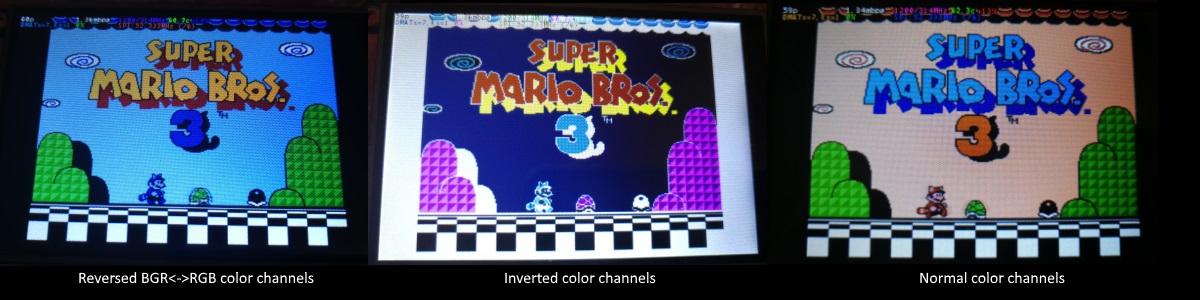
If the color channels are mixed (red is blue, blue is red, green is green) like shown on the left image, pass the CMake option -DDISPLAY_SWAP_BGR=ON to the build.
If the color intensities look wrong (white is black, black is white, color looks like a negative image) like seen in the middle image, pass the CMake option -DDISPLAY_INVERT_COLORS=ON to the build.
If the colors looks off in some other fashion, it is possible that the display is just being driven at a too high SPI bus speed, in which case try making the display run slower by choosing a higher -DSPI_BUS_CLOCK_DIVISOR= option to CMake. Especially on ILI9486 displays it has been observed that the colors on the display can become distorted if the display is run too fast beyond its maximum capability.
fbcp-ili9341 needs a few megabytes of GPU memory to function if DMA transfers are enabled. The gpu_mem boot config option dictates how much of the Pi's memory area is allocated to the GPU. By default this is 64MB, which has been observed to not leave enough memory for fbcp-ili9341 if HDMI is run at 1080p. If this error happens, try increasing GPU memory to eg 128MB by adding a line gpu_mem=128 in /boot/config.txt .
As the number of supported displays, Raspberry Pi device models, Raspbian/Retropie/Lakka OS versions, accompanied C++ compiler versions and fbcp-ili9341 build options have grown in number, there is a combinatorial explosion of all possible build modes that one can put the codebase through, so it is not easy to keep every possible combo tested all the time. Something may have regressed or gotten outdated. Stay calm, and report a bug.
You can also try looking through the commit history to find changes related to your configuration combo, to see if there's a mention of a known good commit in time that should work for your case. If you get an odd compiler error on cmake or make lines, those will usually be very easy to fix, as they are most of the time a result of some configurational oversight.
First, make sure the display is a 4-wire SPI and not a 3-wire one. A display is 4-wire SPI if it has a Data/Control (DC) GPIO line that needs connecting. Sometimes the D/C pin is labeled RS (Register Select). Support for 3-wire SPI displays does exist, but it is experimental and not nearly as well tested as 4-wire displays.
Second is the consideration about display speed. Below is a performance chart of the different displays I have tested. Note that these are sample sizes of one, I don't know how much sample variance there exists. Also I don't know if it is likely that there exists big differences between displays with same controller from different manufacturers. At least the different ILI9341 displays that I have are all quite consistent on performance, whether they are from Adafruit or WaveShare or from BuyDisplay.com.
| Verkäufer | Größe | Auflösung | Regler | Rated SPI Bus Speed | Obtained Bus Speed | Frame Rate |
|---|---|---|---|---|---|---|
| Adafruit PiTFT | 2.8" | 240x320 | ILI9341 | 10MHz | 294MHz/4=73.50MHz | 59.81 fps |
| Adafruit PiTFT | 2.2" | 240x320 | ILI9340 | 15.15MHz | 338MHz/4=84.50MHz | 68.76 fps |
| Adafruit PiTFT | 3.5" | 320x480 | HX8357D | 15.15MHz | 314MHz/6=52.33MHz | 21.29 fps |
| Adafruit OLED | 1.27" | 128x96 | SSD1351 | 20MHz | 360MHz/20=18.00MHz | 91.55 fps |
| Waveshare RPi LCD (B) IPS | 3.5" | 320x480 | ILI9486 | 15.15MHz | 255MHz/8=31.88MHz | 12.97 fps |
| maithoga TFT LCD | 3.5" | 320x480 | ILI9486L | 15.15MHz | 400MHz/8=50.00MHz | 13.56 fps* |
| BuyDisplay.com SPI TFT copy #1 | 3.2" | 240x320 | ILI9341 | 10MHz | 310MHz/4=77.50MHz | 63.07 fps |
| BuyDisplay.com SPI TFT copy #2 | 3.2" | 240x320 | ILI9341 | 10MHz | 300MHz/4=75.00MHz | 61.03 fps |
| Arduino A000096 LCD | 1.77" | 128x160 | ST7735R | 15.15MHz | 355MHz/6=59.16MHz | 180.56 fps |
| Tontec MZ61581-PI-EXT 2016.1.28 | 3.5" | 320x480 | MZ61581 | 128MHz | 280MHz/2=140.00MHz | 56.97 fps |
| Adafruit 240x240 Wide Angle TFT | 1.54" | 240x240 | ST7789 | ? | 340MHz/4=85.00MHz | 92.23 fps |
| WaveShare 240x240 Display HAT | 1.3" | 240x240 | ST7789VW | 62.5MHz | 338MHz/4=84.50MHz | 91.69 fps |
| WaveShare 128x128 Display HAT | 1.44" | 128x128 | ST7735S | 15.15MHz | (ungetestet) | (ungetestet) |
| KeDei v6.3 | 3.5" | 320x480 | MPI3501 | ? | 400MHz/12=33.333MHz | 4.8fps ** |
In this list, Rated SPI Bus Speed is the maximum clock speed that the display controller is rated to run at. The Obtained Bus Speed column lists the fastest SPI bus speed that was achieved in practice, and the core_freq BCM Core speed and SPI Clock Divider CDIV setting that was used to achieve that rate. Note how most display controllers can generally be driven much faster than what they are officially rated at in their spec sheets.
The Frame Rate column shows the worst case frame rate when full screen updates are being performed. This occurs for example when watching fullscreen video (that is not a flat colored cartoon). Because fbcp-ili9341 only sends over the pixels that have changed, displays such as HX8357D and ILI9486 can still be used to play many games at 60fps. Retro games work especially well.
All the ILI9341 displays work nice and super fast at ~70-80MHz. My WaveShare 3.5" 320x480 ILI9486 display runs really slow compared to its pixel resolution, ~32MHz only. See fbcp-ili9341 ported to ILI9486 WaveShare 3.5" (B) SpotPear 320x480 SPI display for a video of this display in action. Adafruit's 320x480 3.5" HX8357D PiTFTs is ~64% faster in comparison.
The ILI9486L controller based maithoga display runs a bit faster than ILI9486 WaveShare, 50MHz versus 31.88MHz, ie +56.8% bandwidth increase. However fps-wise maithoga reaches only 13.56 vs WaveShare 12.97 fps, because the bandwidth advantage is fully lost in pixel format differences: ILI9486L requires transmitting 24 bits per each pixel (R6G6B6 mode), whereas ILI9486 supports 16 bits per pixel R5G6B5 mode. This is reflected in the above chart refresh rate for the maithoga display (marked with a star).
If manufacturing variances turn out not to be high between copies, and you'd like to have a bigger 320x480 display instead of a 240x320 one, then it is recommended to avoid ILI9486, they indeed are slow.
The KeDei v6.3 display with MPI3501 controller takes the crown of being horrible, in all aspects imaginable. It is able to run at 33.33 MHz, but due to technical design limitations of the display (see #40), effective bus speed is halved, and only about 72% utilization of the remaining bus rate is achieved. DMA cannot be used, so CPU usage will be off the charts. Even though fbcp-ili9341 supports this display, level of support is expected to be poor, because the hardware design is a closed secret without open documentation publicly available from the manufacturer. Stay clear of KeDei or MPI3501 displays.
The Tontec MZ61581 controller based 320x480 3.5" display on the other hand can be driven insanely fast at up to 140MHz! These seem to be quite hard to come by though and they are expensive. Tontec seems to have gone out of business and for example the domain itontec.com from which the supplied instructions sheet asks to download original drivers from is no longer registered. I was able to find one from eBay for testing.
Search around, or ask the manufacturer of the display what the maximum SPI bus speed is for the device. This is the most important aspect to getting good frame rates, but unfortunately most web links never state the SPI speed rating, or they state it ridiculously low like in the spec sheets. Try and buy to see, or ask in some community forums from people who already have a particular display to find out what SPI bus speed it can achieve.
One might think that since Pi Zero is slower than a Pi 3, the SPI bus speed might not matter as much when running on a Pi Zero, but the effect is rather the opposite. To get good framerates on a Pi Zero, it should be paired with a display with as high SPI bus speed capability as possible. This is because the higher the SPI bus speed is, the more autonomously a DMA controller can drive it without CPU intervention. For the same reason, the interlacing technique does not (currently at least) perform well on a Pi Zero, so it is disabled there by default. ILI9341s run well on Pi Zero, ILI9486 on the other hand is quite difficult to combine with a Pi Zero.
Ultimately, it should be noted that parallel displays (DPI) are the proper method for getting fast framerates easily. SPI displays should only be preferred if display form factor is important and a desired product might only exist as SPI and not as DPI, or the number of GPIO pins that are available on the Pi is scarce that sacrificing dozens of pins to RGB data is not machbar.
Hardware-wise, there are six different ways to connect displays to the Pi. Here are the pros and cons of each:
Displays are generally manufactured to utilize one specific interfacing method, with the exception that some displays have a both I²C and SPI modes that can be configured via soldering.
Fbcp-ili9341 driver is about interfacing with SPI displays. If your display utilizes some other connection mechanism, fbcp-ili9341 will not apply.
Software-wise, there are two possible alternatives to fbcp-ili9341:
The following links proved helpful when writing this:
If you would like to help push Raspberry Pi SPI display support further, there are always more things to do in the project. Here is a list of ideas and TODOs for recognized work items to contribute, roughly rated in order of increasing difficulty.
top / htop , or with a power meter off the wall and report the results.SPI_3WIRE_PROTOCOL + ALL_TASKS_SHOULD_DMA to work together, or 3) fix up SPI_3WIRE_PROTOCOL + OFFLOAD_PIXEL_COPY_TO_DMA_CPP to work together.ALL_TASKS_SHOULD_DMA mode to be always superior in performance and CPU usage so that the non- ALL_TASKS_SHOULD_DMA path can be dropped from the codebase. (probably requires the above chaining to function efficiently)This driver is licensed under the MIT License. See LICENSE.txt. In nonlegal terms, it's yours for both free and commercial projects, DIY packages, kickstarters, Etsys and Ebays, and you don't owe back a dime. Feel free to apply and derive as you wish.
If you found fbcp-ili9341 useful, it makes me happy to hear back about the projects it found a home in. If you did a build or a project where fbcp-ili9341 worked out, it'd be great to see a video or some photos or read about your experiences.
I hope you build something you enjoy!
Best way to discuss the driver is to open a GitHub issue. You may also be able to find me over at sudomod.com Discord channel.


