system design 101
1.0.0
【 ?? YouTube | ? Newsletter 】
Explain complex systems using visuals and simple terms.
Whether you're preparing for a System Design Interview or you simply want to understand how systems work beneath the surface, we hope this repository will help you achieve that.
Architecture styles define how different components of an application programming interface (API) interact with one another. As a result, they ensure efficiency, reliability, and ease of integration with other systems by providing a standard approach to designing and building APIs. Here are the most used styles:
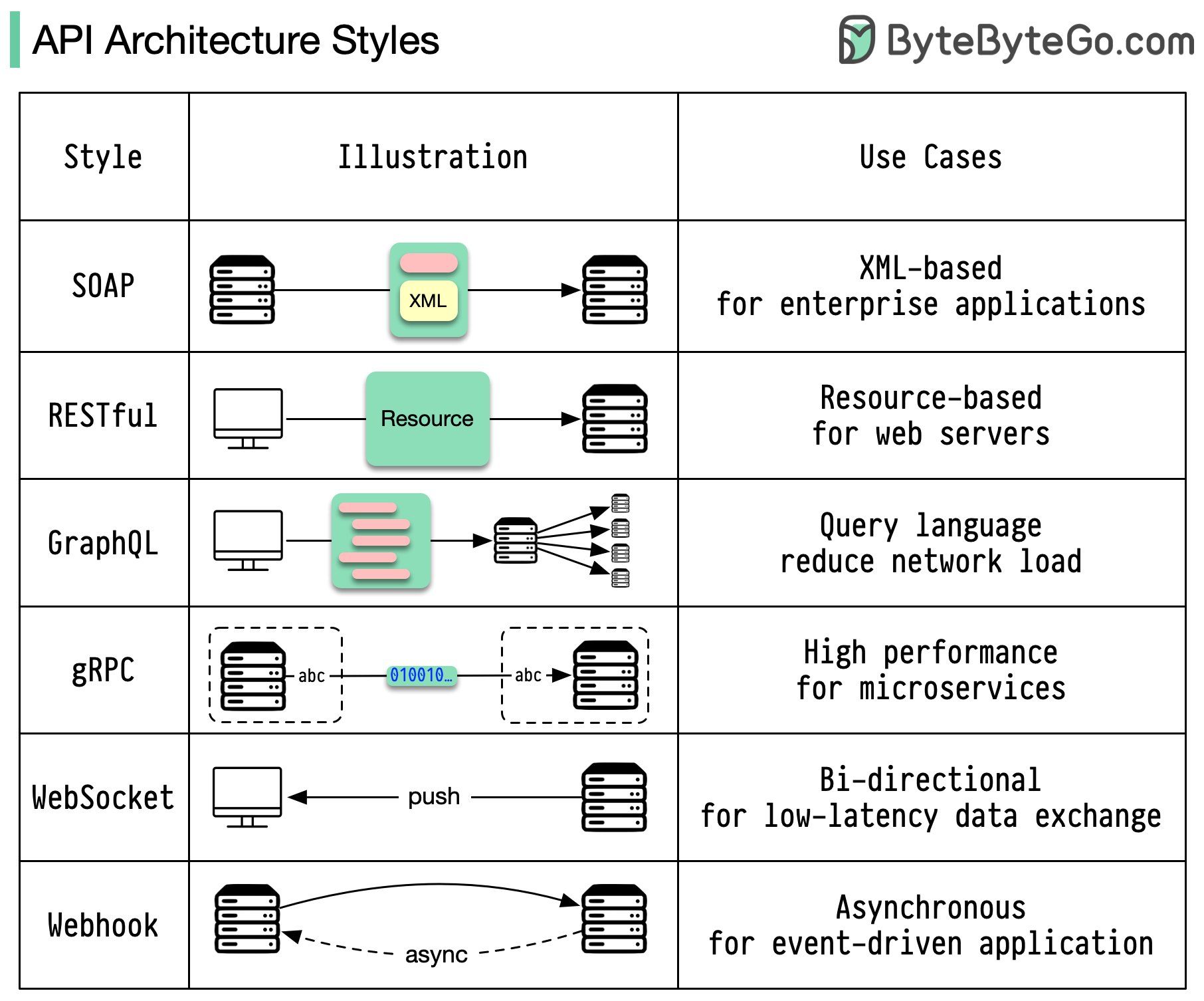
SOAP:
Mature, comprehensive, XML-based
Best for enterprise applications
RESTful:
Popular, easy-to-implement, HTTP methods
Ideal for web services
GraphQL:
Query language, request specific data
Reduces network overhead, faster responses
gRPC:
Modern, high-performance, Protocol Buffers
Suitable for microservices architectures
WebSocket:
Real-time, bidirectional, persistent connections
Perfect for low-latency data exchange
Webhook:
Event-driven, HTTP callbacks, asynchronous
Notifies systems when events occur
When it comes to API design, REST and GraphQL each have their own strengths and weaknesses.
The diagram below shows a quick comparison between REST and GraphQL.
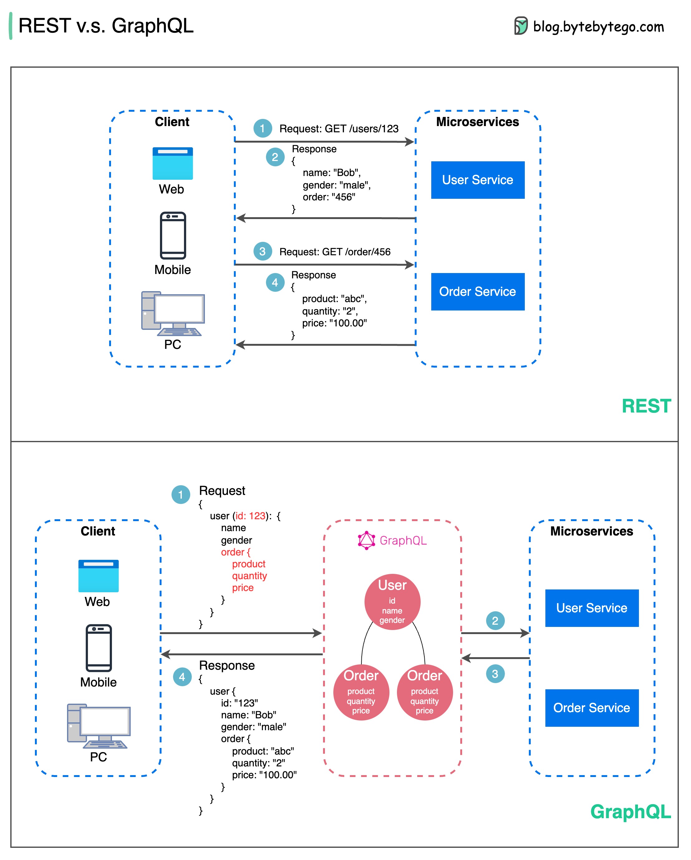
REST
GraphQL
The best choice between REST and GraphQL depends on the specific requirements of the application and development team. GraphQL is a good fit for complex or frequently changing frontend needs, while REST suits applications where simple and consistent contracts are preferred.
Neither API approach is a silver bullet. Carefully evaluating requirements and tradeoffs is important to pick the right style. Both REST and GraphQL are valid options for exposing data and powering modern applications.
RPC (Remote Procedure Call) is called “remote” because it enables communications between remote services when services are deployed to different servers under microservice architecture. From the user’s point of view, it acts like a local function call.
The diagram below illustrates the overall data flow for gRPC.
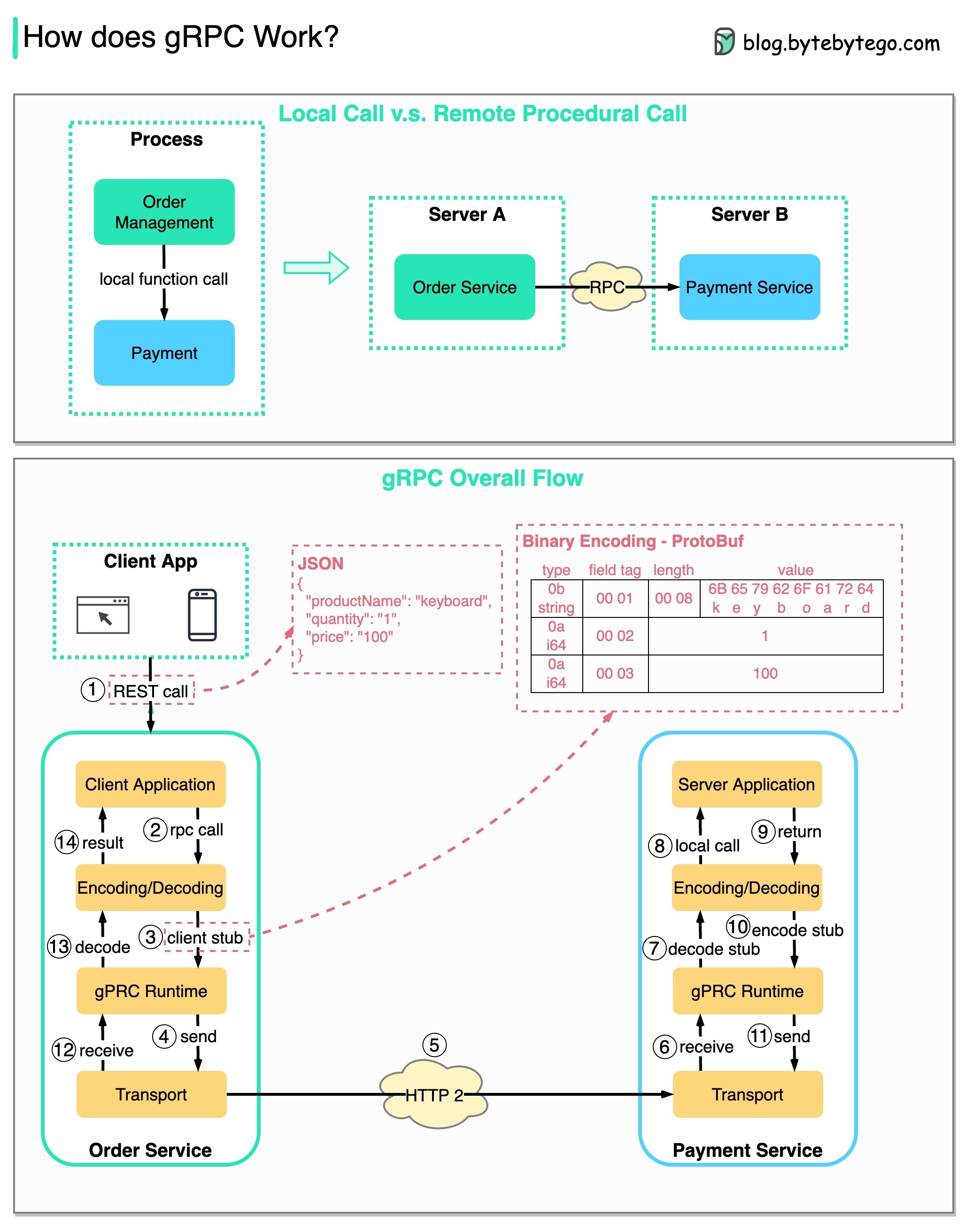
Step 1: A REST call is made from the client. The request body is usually in JSON format.
Steps 2 - 4: The order service (gRPC client) receives the REST call, transforms it, and makes an RPC call to the payment service. gRPC encodes the client stub into a binary format and sends it to the low-level transport layer.
Step 5: gRPC sends the packets over the network via HTTP2. Because of binary encoding and network optimizations, gRPC is said to be 5X faster than JSON.
Steps 6 - 8: The payment service (gRPC server) receives the packets from the network, decodes them, and invokes the server application.
Steps 9 - 11: The result is returned from the server application, and gets encoded and sent to the transport layer.
Steps 12 - 14: The order service receives the packets, decodes them, and sends the result to the client application.
The diagram below shows a comparison between polling and Webhook.
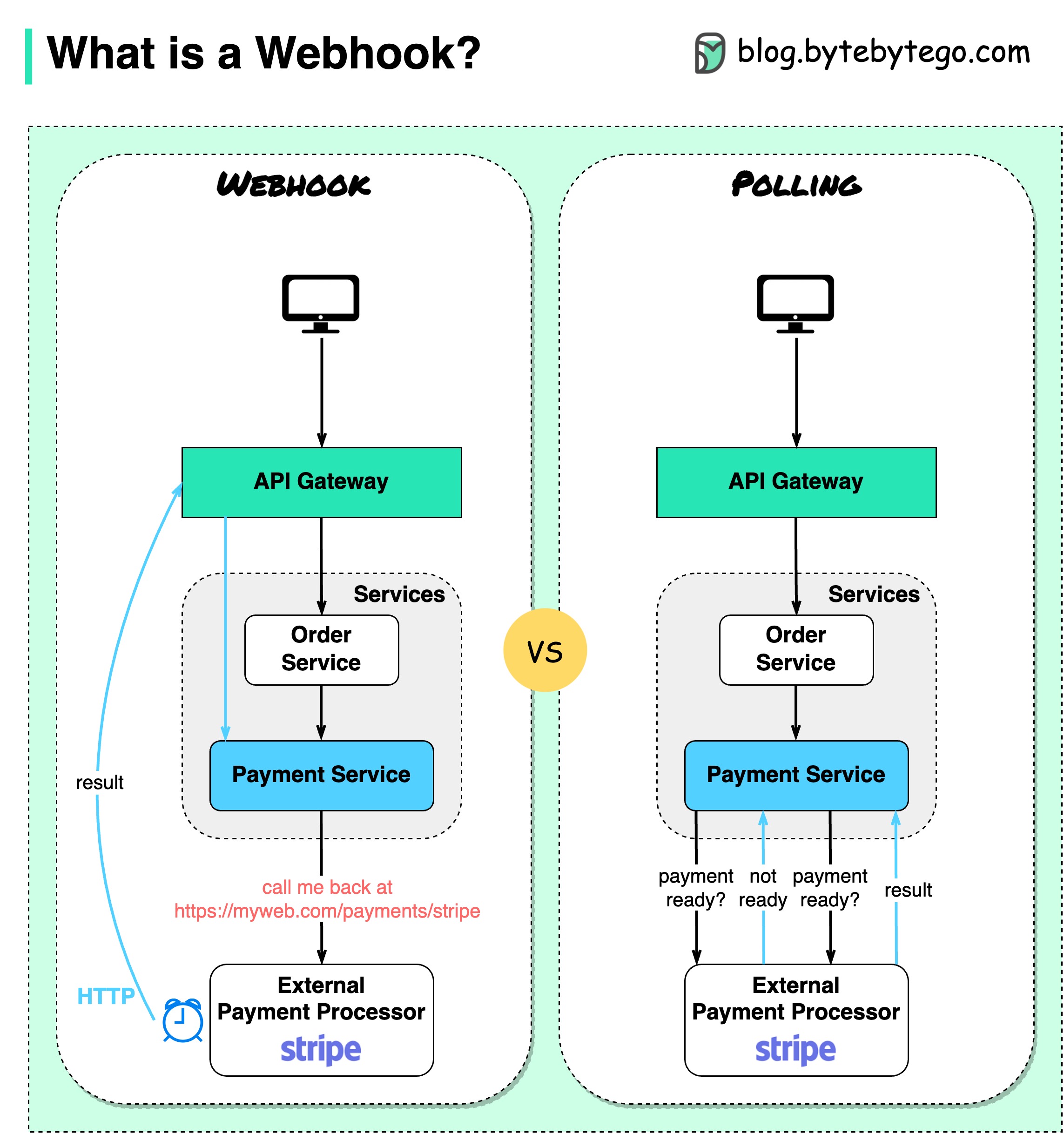
Assume we run an eCommerce website. The clients send orders to the order service via the API gateway, which goes to the payment service for payment transactions. The payment service then talks to an external payment service provider (PSP) to complete the transactions.
There are two ways to handle communications with the external PSP.
1. Short polling
After sending the payment request to the PSP, the payment service keeps asking the PSP about the payment status. After several rounds, the PSP finally returns with the status.
Short polling has two drawbacks:
2. Webhook
We can register a webhook with the external service. It means: call me back at a certain URL when you have updates on the request. When the PSP has completed the processing, it will invoke the HTTP request to update the payment status.
In this way, the programming paradigm is changed, and the payment service doesn’t need to waste resources to poll the payment status anymore.
What if the PSP never calls back? We can set up a housekeeping job to check payment status every hour.
Webhooks are often referred to as reverse APIs or push APIs because the server sends HTTP requests to the client. We need to pay attention to 3 things when using a webhook:
The diagram below shows 5 common tricks to improve API performance.
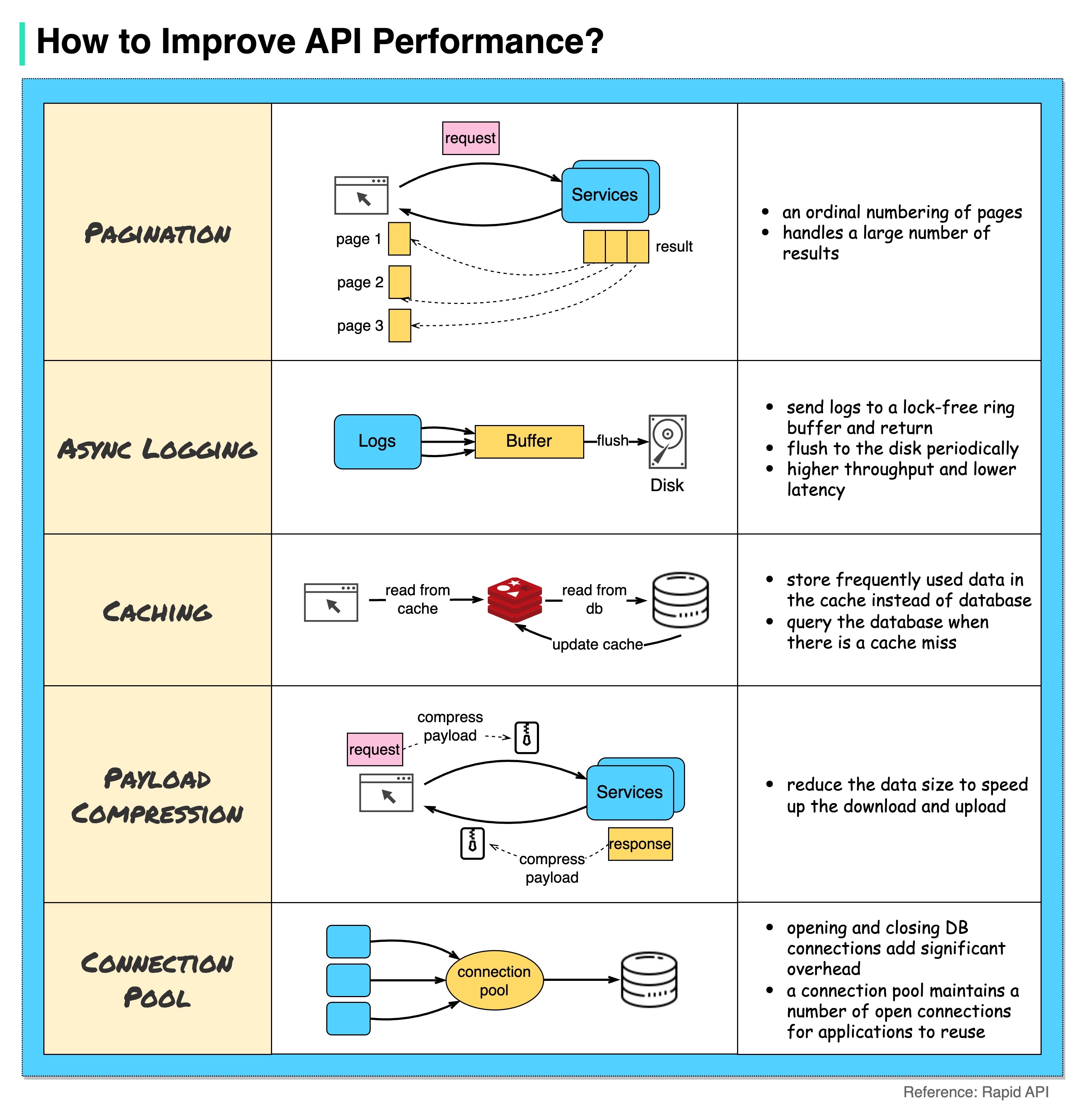
Pagination
This is a common optimization when the size of the result is large. The results are streaming back to the client to improve the service responsiveness.
Asynchronous Logging
Synchronous logging deals with the disk for every call and can slow down the system. Asynchronous logging sends logs to a lock-free buffer first and immediately returns. The logs will be flushed to the disk periodically. This significantly reduces the I/O overhead.
Caching
We can store frequently accessed data into a cache. The client can query the cache first instead of visiting the database directly. If there is a cache miss, the client can query from the database. Caches like Redis store data in memory, so the data access is much faster than the database.
Payload Compression
The requests and responses can be compressed using gzip etc so that the transmitted data size is much smaller. This speeds up the upload and download.
Connection Pool
When accessing resources, we often need to load data from the database. Opening the closing db connections adds significant overhead. So we should connect to the db via a pool of open connections. The connection pool is responsible for managing the connection lifecycle.
What problem does each generation of HTTP solve?
The diagram below illustrates the key features.
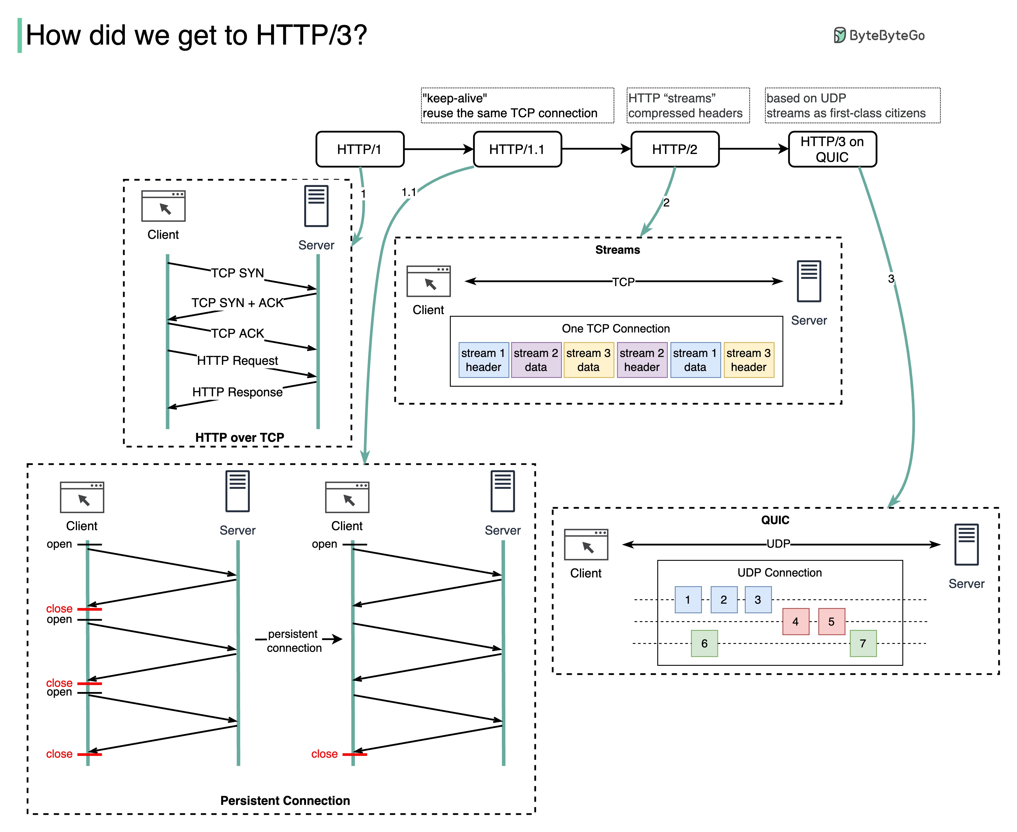
HTTP 1.0 was finalized and fully documented in 1996. Every request to the same server requires a separate TCP connection.
HTTP 1.1 was published in 1997. A TCP connection can be left open for reuse (persistent connection), but it doesn’t solve the HOL (head-of-line) blocking issue.
HOL blocking - when the number of allowed parallel requests in the browser is used up, subsequent requests need to wait for the former ones to complete.
HTTP 2.0 was published in 2015. It addresses HOL issue through request multiplexing, which eliminates HOL blocking at the application layer, but HOL still exists at the transport (TCP) layer.
As you can see in the diagram, HTTP 2.0 introduced the concept of HTTP “streams”: an abstraction that allows multiplexing different HTTP exchanges onto the same TCP connection. Each stream doesn’t need to be sent in order.
HTTP 3.0 first draft was published in 2020. It is the proposed successor to HTTP 2.0. It uses QUIC instead of TCP for the underlying transport protocol, thus removing HOL blocking in the transport layer.
QUIC is based on UDP. It introduces streams as first-class citizens at the transport layer. QUIC streams share the same QUIC connection, so no additional handshakes and slow starts are required to create new ones, but QUIC streams are delivered independently such that in most cases packet loss affecting one stream doesn't affect others.
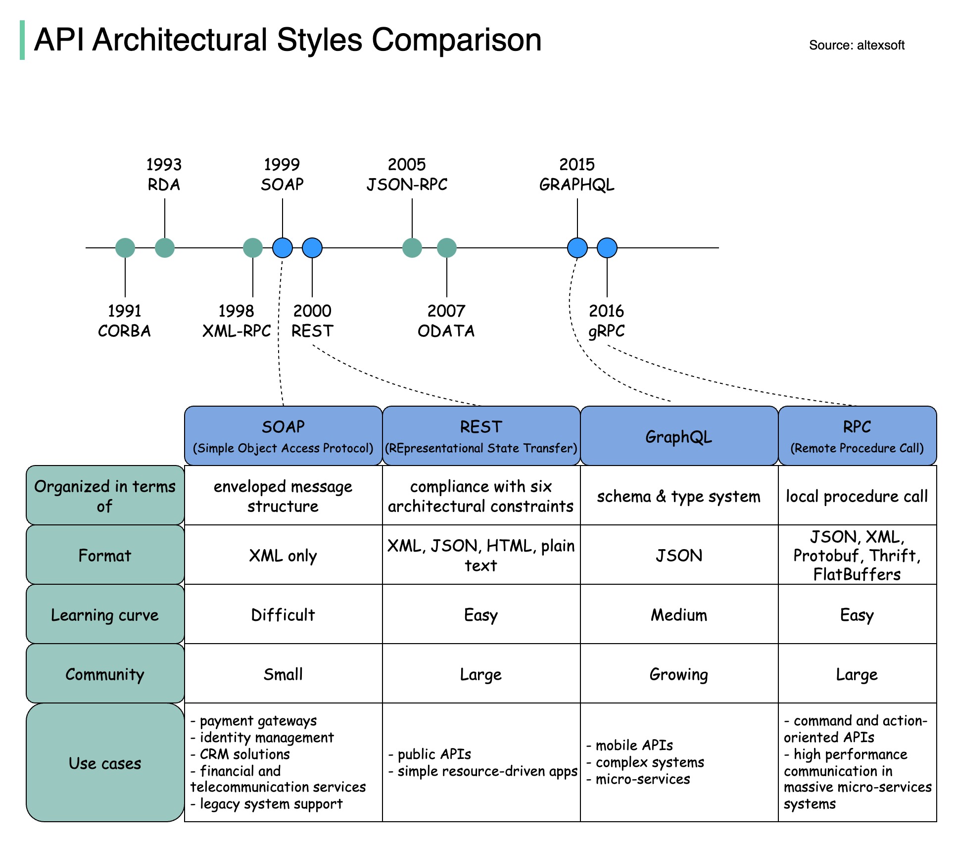
The diagram below illustrates the API timeline and API styles comparison.
Over time, different API architectural styles are released. Each of them has its own patterns of standardizing data exchange.
You can check out the use cases of each style in the diagram.
The diagram below shows the differences between code-first development and API-first development. Why do we want to consider API first design?
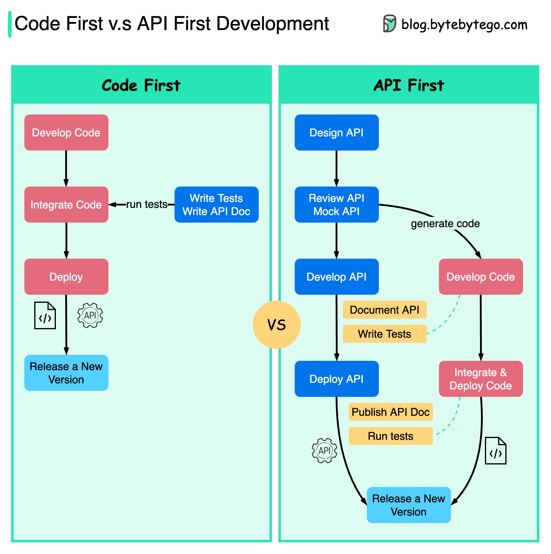
It is better to think through the system's complexity before writing the code and carefully defining the boundaries of the services.
We can mock requests and responses to validate the API design before writing code.
Developers are happy about the process as well because they can focus on functional development instead of negotiating sudden changes.
The possibility of having surprises toward the end of the project lifecycle is reduced.
Because we have designed the API first, the tests can be designed while the code is being developed. In a way, we also have TDD (Test Driven Design) when using API first development.
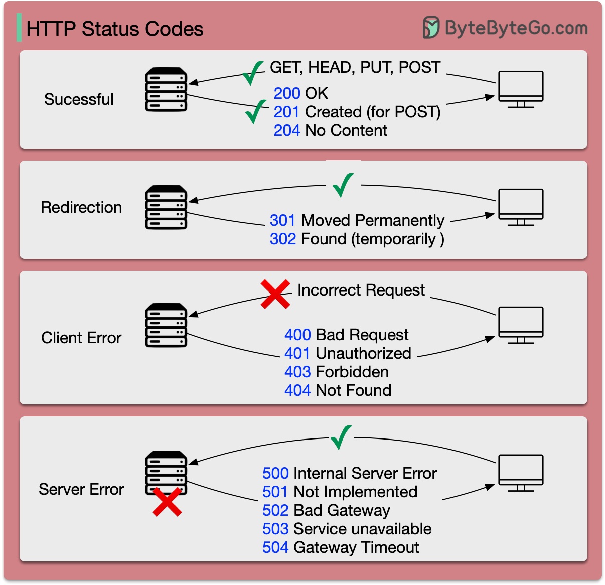
The response codes for HTTP are divided into five categories:
Informational (100-199) Success (200-299) Redirection (300-399) Client Error (400-499) Server Error (500-599)
The diagram below shows the details.
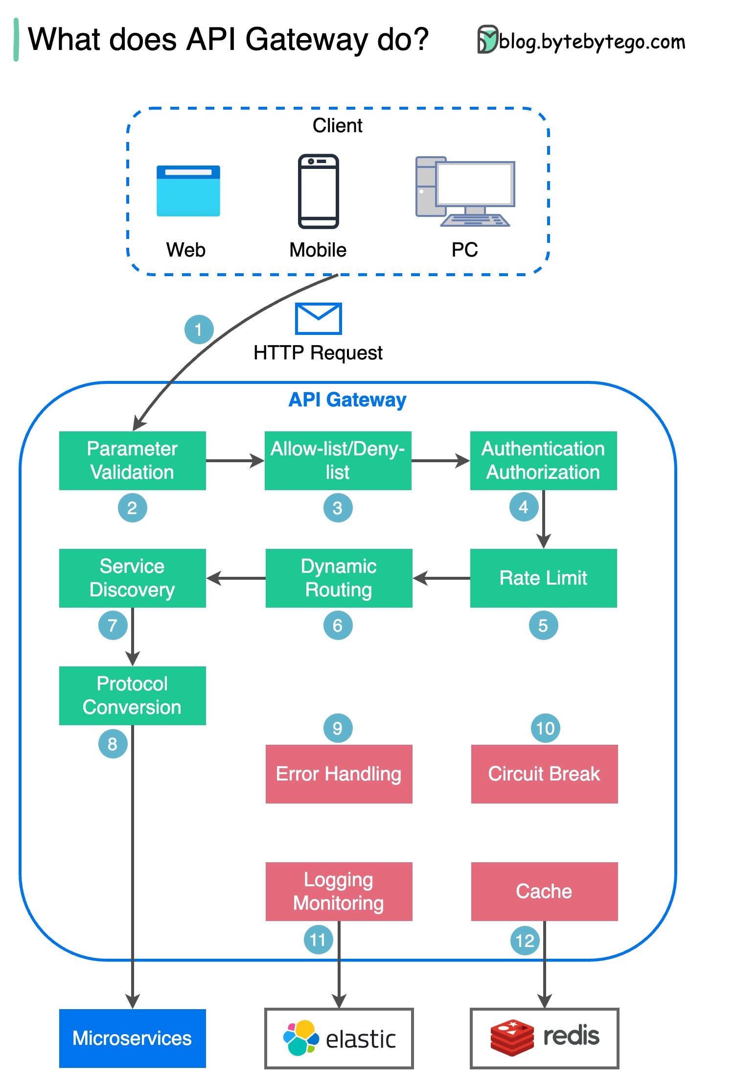
Step 1 - The client sends an HTTP request to the API gateway.
Step 2 - The API gateway parses and validates the attributes in the HTTP request.
Step 3 - The API gateway performs allow-list/deny-list checks.
Step 4 - The API gateway talks to an identity provider for authentication and authorization.
Step 5 - The rate limiting rules are applied to the request. If it is over the limit, the request is rejected.
Steps 6 and 7 - Now that the request has passed basic checks, the API gateway finds the relevant service to route to by path matching.
Step 8 - The API gateway transforms the request into the appropriate protocol and sends it to backend microservices.
Steps 9-12: The API gateway can handle errors properly, and deals with faults if the error takes a longer time to recover (circuit break). It can also leverage ELK (Elastic-Logstash-Kibana) stack for logging and monitoring. We sometimes cache data in the API gateway.
The diagram below shows typical API designs with a shopping cart example.
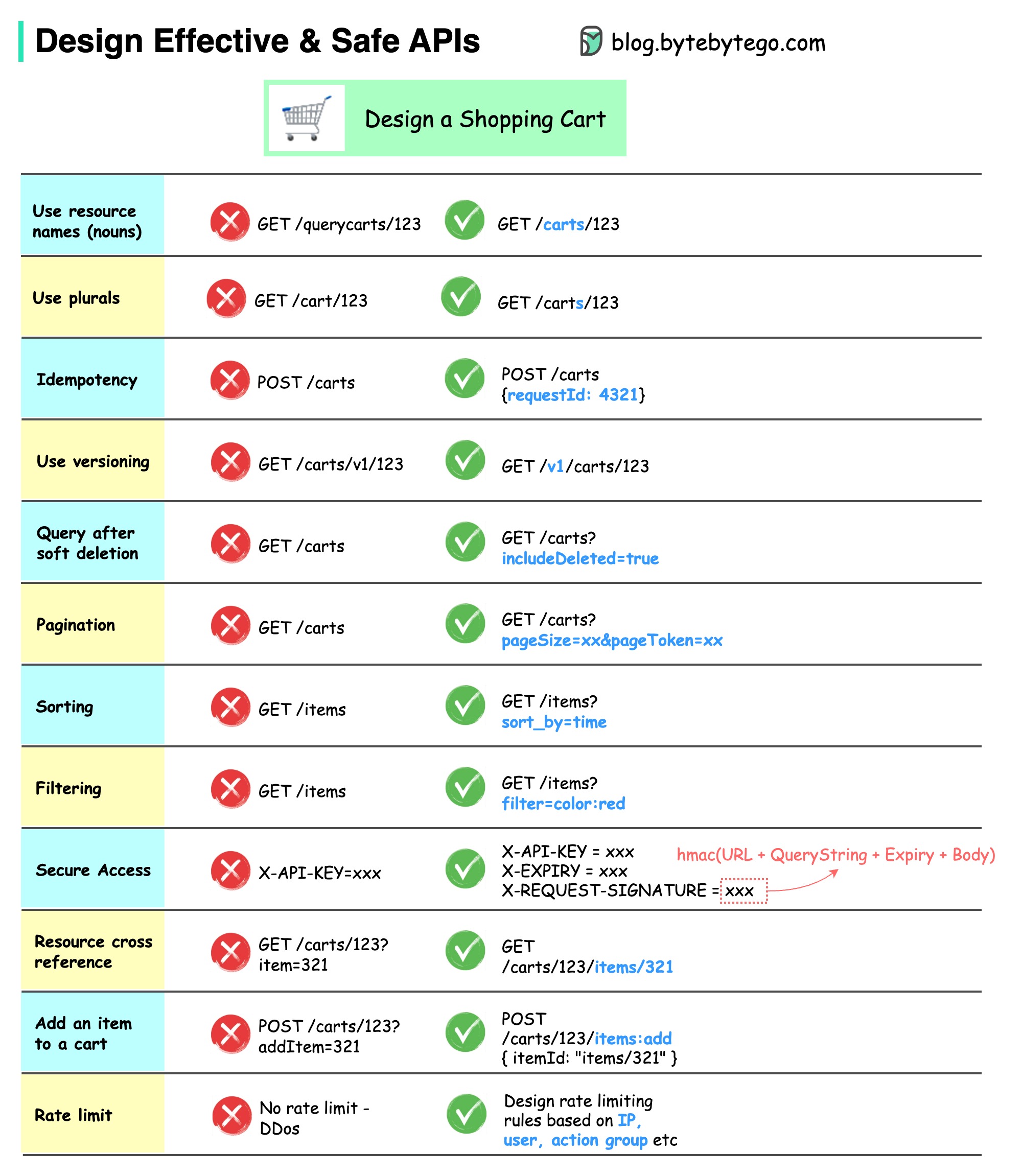
Note that API design is not just URL path design. Most of the time, we need to choose the proper resource names, identifiers, and path patterns. It is equally important to design proper HTTP header fields or to design effective rate-limiting rules within the API gateway.
How is data sent over the network? Why do we need so many layers in the OSI model?
The diagram below shows how data is encapsulated and de-encapsulated when transmitting over the network.
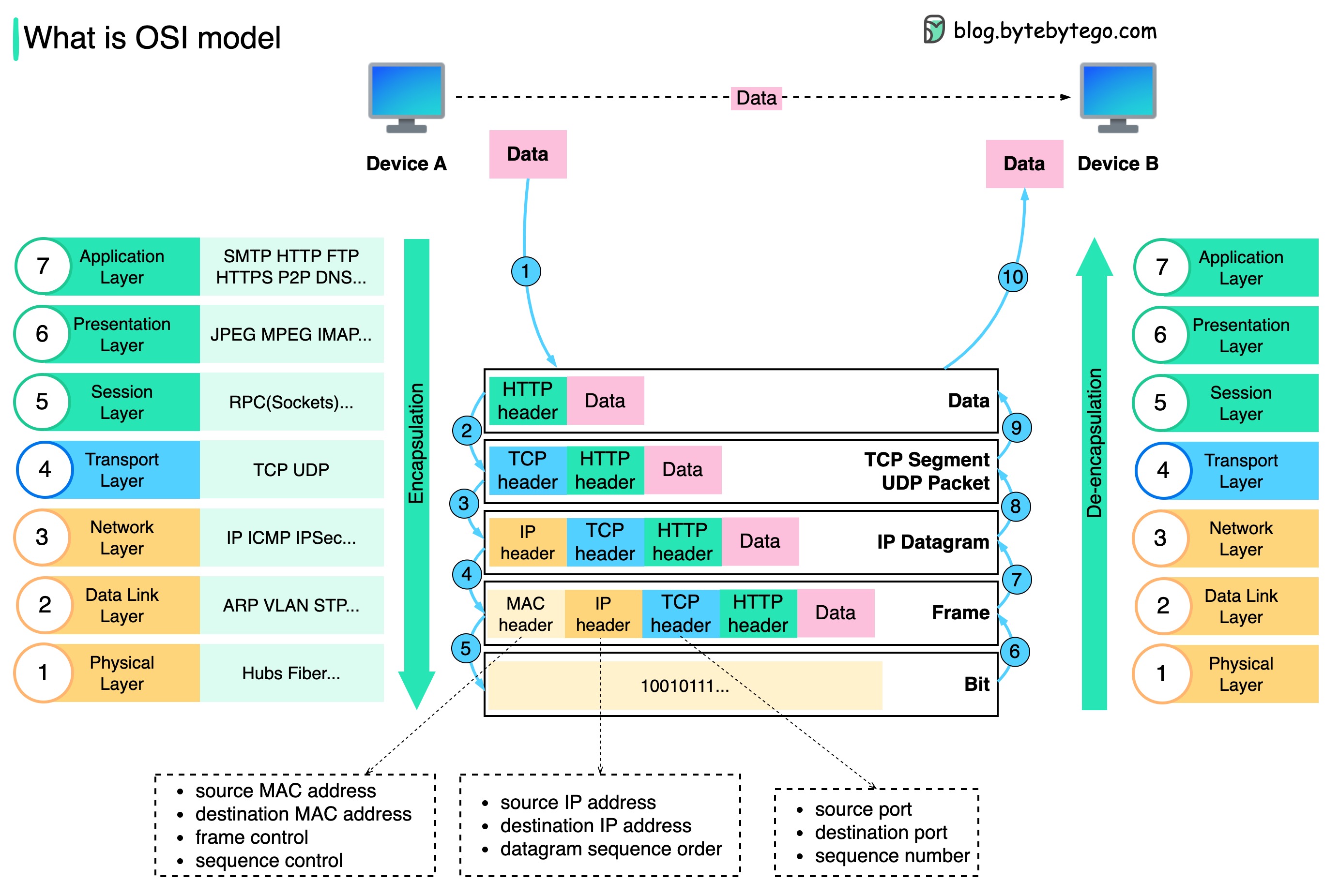
Step 1: When Device A sends data to Device B over the network via the HTTP protocol, it is first added an HTTP header at the application layer.
Step 2: Then a TCP or a UDP header is added to the data. It is encapsulated into TCP segments at the transport layer. The header contains the source port, destination port, and sequence number.
Step 3: The segments are then encapsulated with an IP header at the network layer. The IP header contains the source/destination IP addresses.
Step 4: The IP datagram is added a MAC header at the data link layer, with source/destination MAC addresses.
Step 5: The encapsulated frames are sent to the physical layer and sent over the network in binary bits.
Steps 6-10: When Device B receives the bits from the network, it performs the de-encapsulation process, which is a reverse processing of the encapsulation process. The headers are removed layer by layer, and eventually, Device B can read the data.
We need layers in the network model because each layer focuses on its own responsibilities. Each layer can rely on the headers for processing instructions and does not need to know the meaning of the data from the last layer.
The diagram below shows the differences between a ??????? ????? and a ??????? ?????.
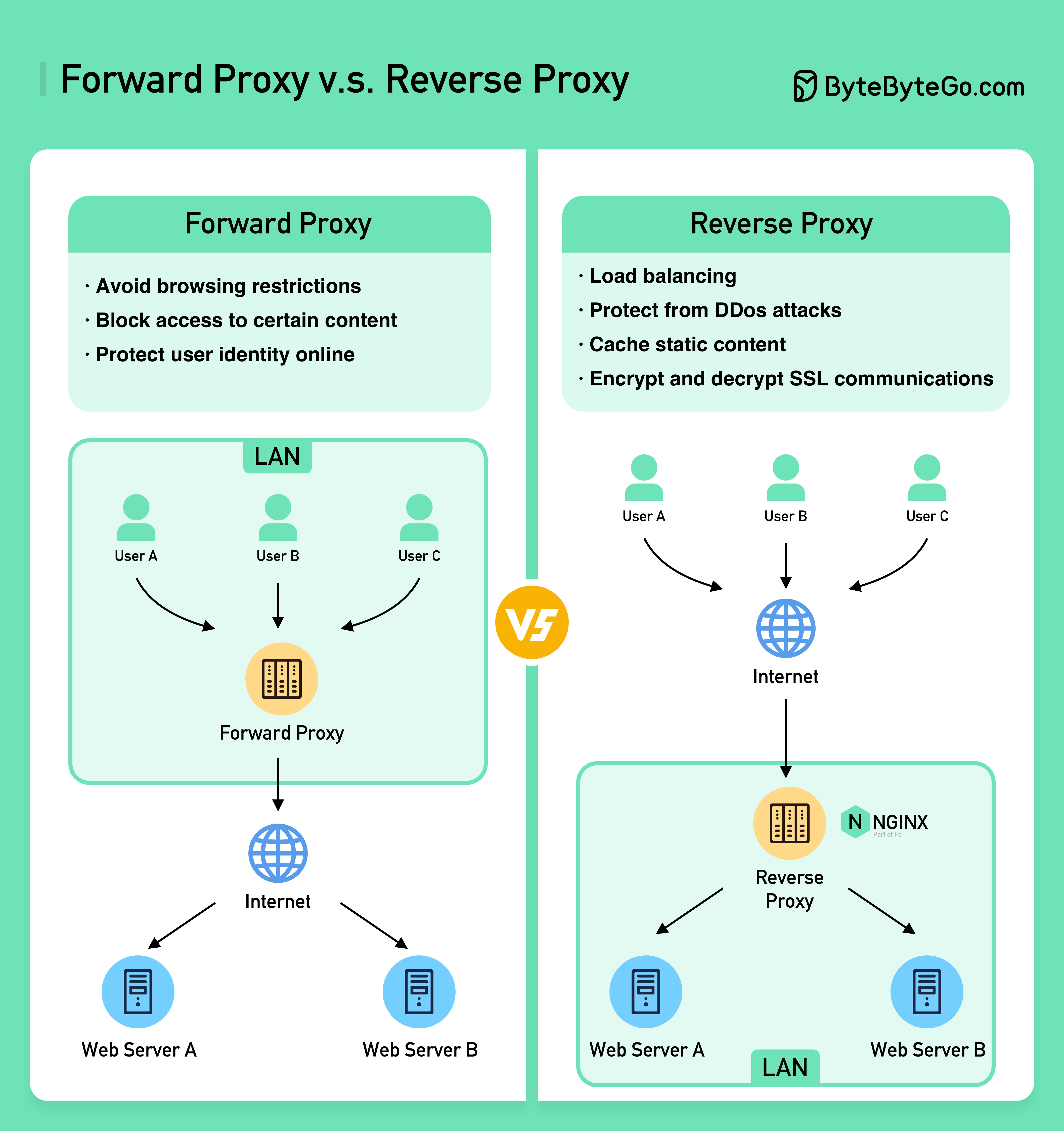
A forward proxy is a server that sits between user devices and the internet.
A forward proxy is commonly used for:
A reverse proxy is a server that accepts a request from the client, forwards the request to web servers, and returns the results to the client as if the proxy server had processed the request.
A reverse proxy is good for:
The diagram below shows 6 common algorithms.
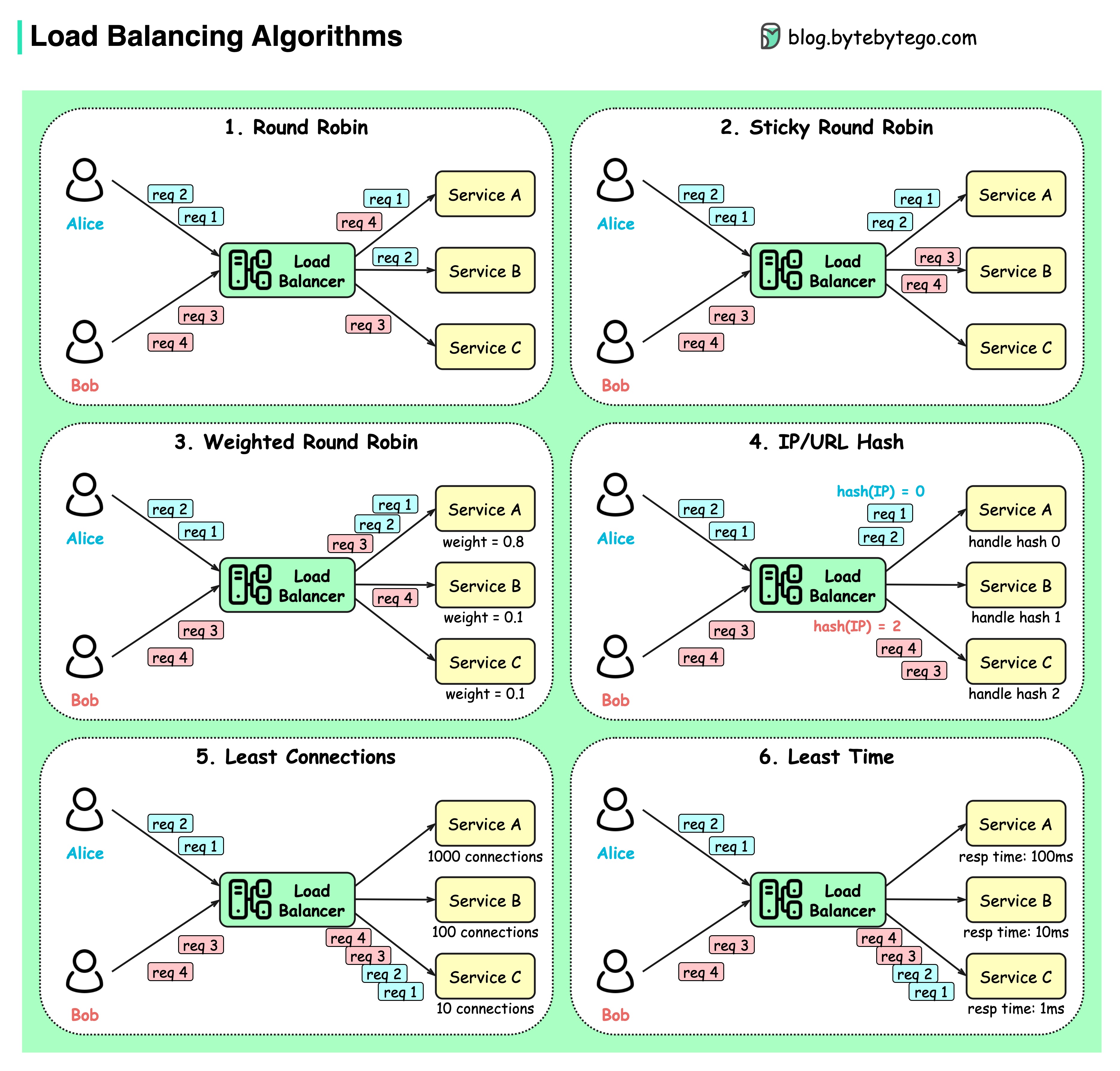
Round robin
The client requests are sent to different service instances in sequential order. The services are usually required to be stateless.
Sticky round-robin
This is an improvement of the round-robin algorithm. If Alice’s first request goes to service A, the following requests go to service A as well.
Weighted round-robin
The admin can specify the weight for each service. The ones with a higher weight handle more requests than others.
Hash
This algorithm applies a hash function on the incoming requests’ IP or URL. The requests are routed to relevant instances based on the hash function result.
Least connections
A new request is sent to the service instance with the least concurrent connections.
Least response time
A new request is sent to the service instance with the fastest response time.
The diagram below shows a comparison of URL, URI, and URN.
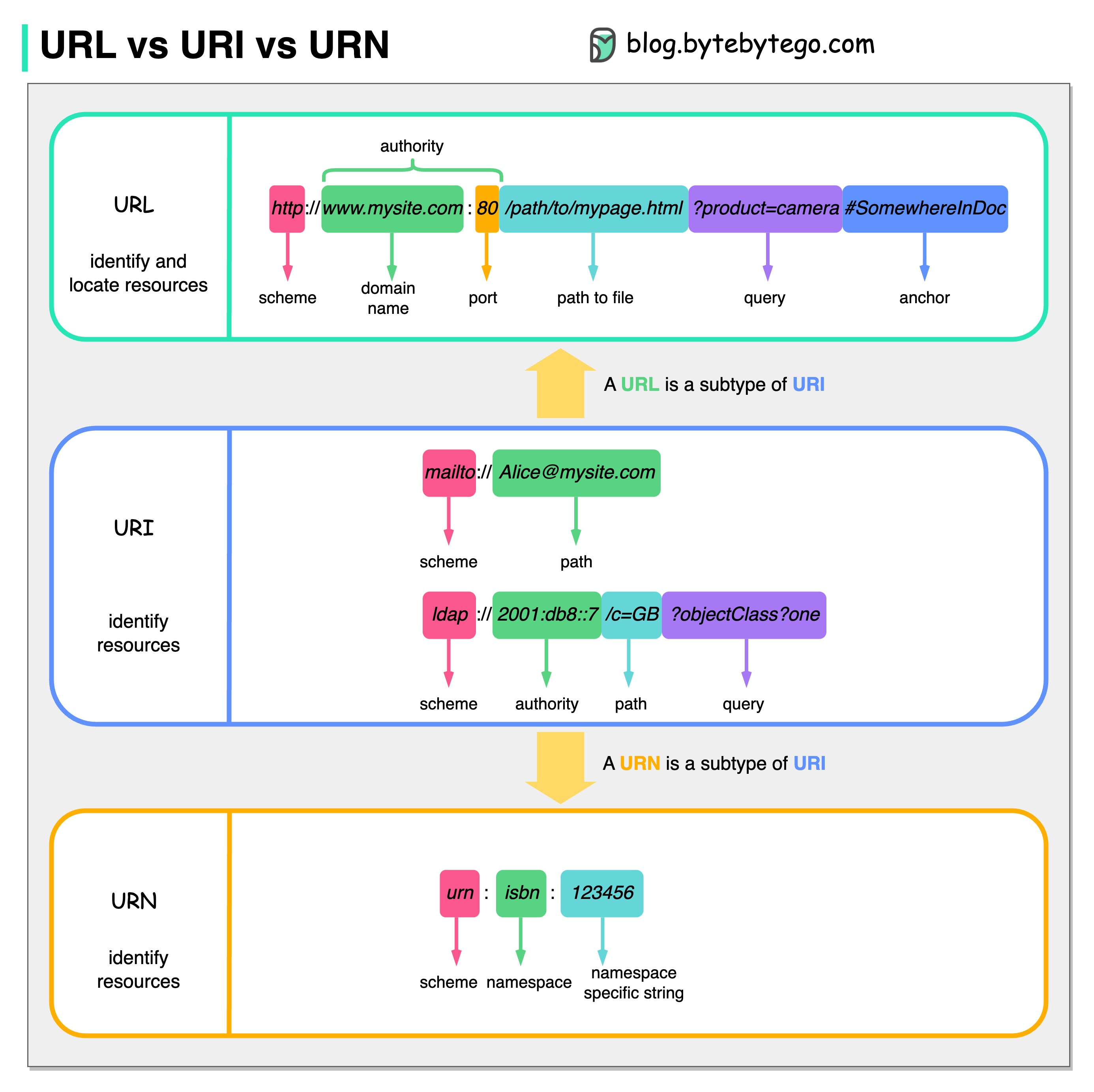
URI stands for Uniform Resource Identifier. It identifies a logical or physical resource on the web. URL and URN are subtypes of URI. URL locates a resource, while URN names a resource.
A URI is composed of the following parts: scheme:[//authority]path[?query][#fragment]
URL stands for Uniform Resource Locator, the key concept of HTTP. It is the address of a unique resource on the web. It can be used with other protocols like FTP and JDBC.
URN stands for Uniform Resource Name. It uses the urn scheme. URNs cannot be used to locate a resource. A simple example given in the diagram is composed of a namespace and a namespace-specific string.
If you would like to learn more detail on the subject, I would recommend W3C’s clarification.
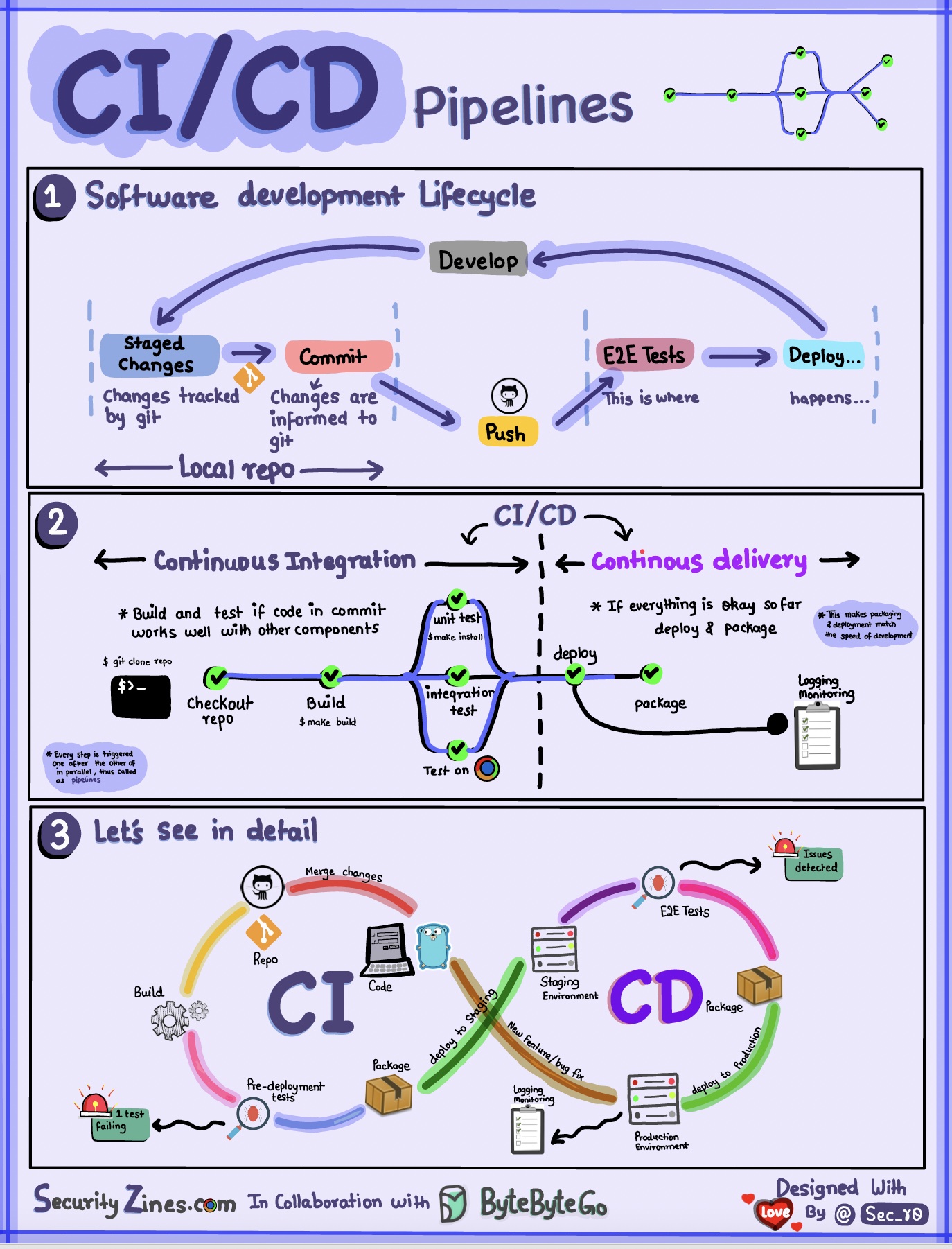
Section 1 - SDLC with CI/CD
The software development life cycle (SDLC) consists of several key stages: development, testing, deployment, and maintenance. CI/CD automates and integrates these stages to enable faster and more reliable releases.
When code is pushed to a git repository, it triggers an automated build and test process. End-to-end (e2e) test cases are run to validate the code. If tests pass, the code can be automatically deployed to staging/production. If issues are found, the code is sent back to development for bug fixing. This automation provides fast feedback to developers and reduces the risk of bugs in production.
Section 2 - Difference between CI and CD
Continuous Integration (CI) automates the build, test, and merge process. It runs tests whenever code is committed to detect integration issues early. This encourages frequent code commits and rapid feedback.
Continuous Delivery (CD) automates release processes like infrastructure changes and deployment. It ensures software can be released reliably at any time through automated workflows. CD may also automate the manual testing and approval steps required before production deployment.
Section 3 - CI/CD Pipeline
A typical CI/CD pipeline has several connected stages:
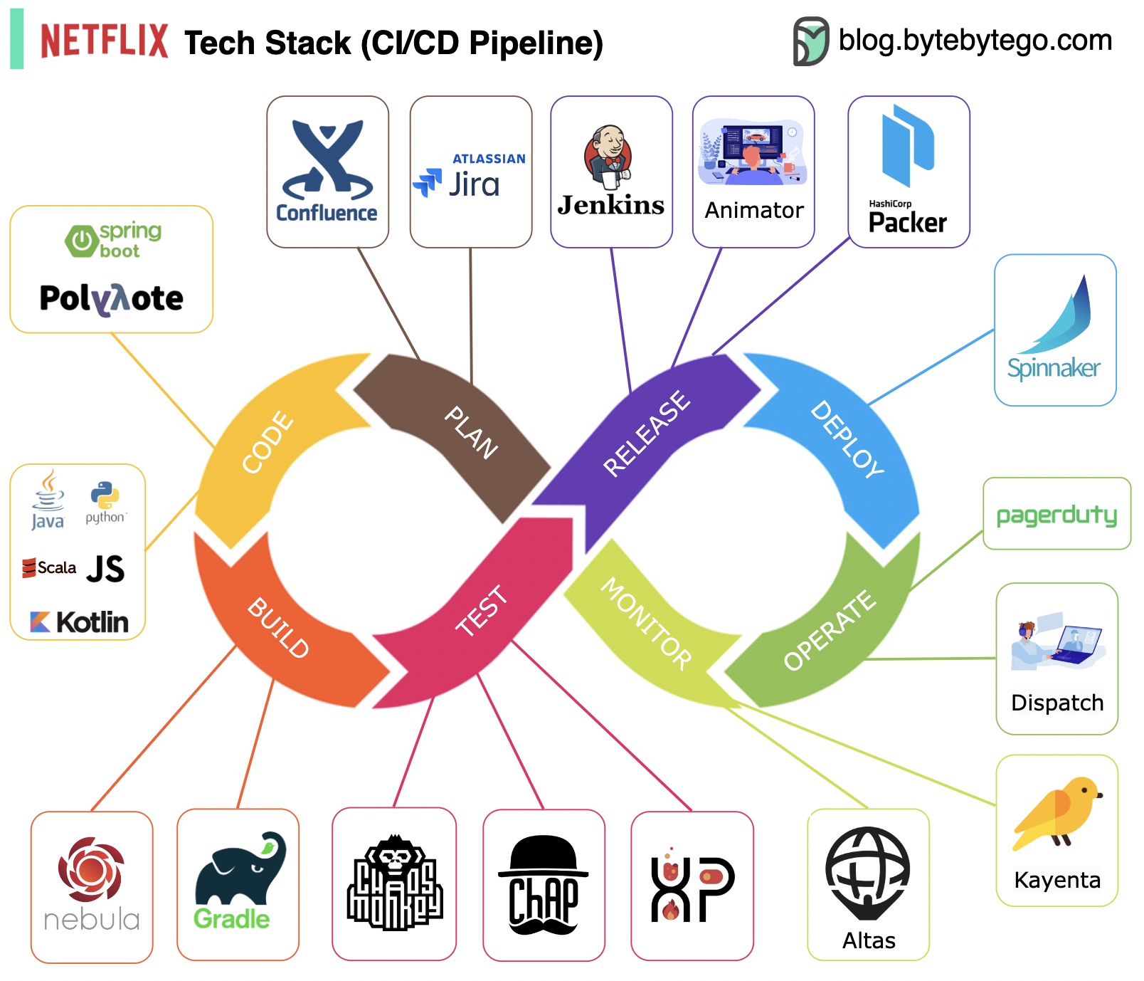
Planning: Netflix Engineering uses JIRA for planning and Confluence for documentation.
Coding: Java is the primary programming language for the backend service, while other languages are used for different use cases.
Build: Gradle is mainly used for building, and Gradle plugins are built to support various use cases.
Packaging: Package and dependencies are packed into an Amazon Machine Image (AMI) for release.
Testing: Testing emphasizes the production culture's focus on building chaos tools.
Deployment: Netflix uses its self-built Spinnaker for canary rollout deployment.
Monitoring: The monitoring metrics are centralized in Atlas, and Kayenta is used to detect anomalies.
Incident report: Incidents are dispatched according to priority, and PagerDuty is used for incident handling.
These architecture patterns are among the most commonly used in app development, whether on iOS or Android platforms. Developers have introduced them to overcome the limitations of earlier patterns. So, how do they differ?
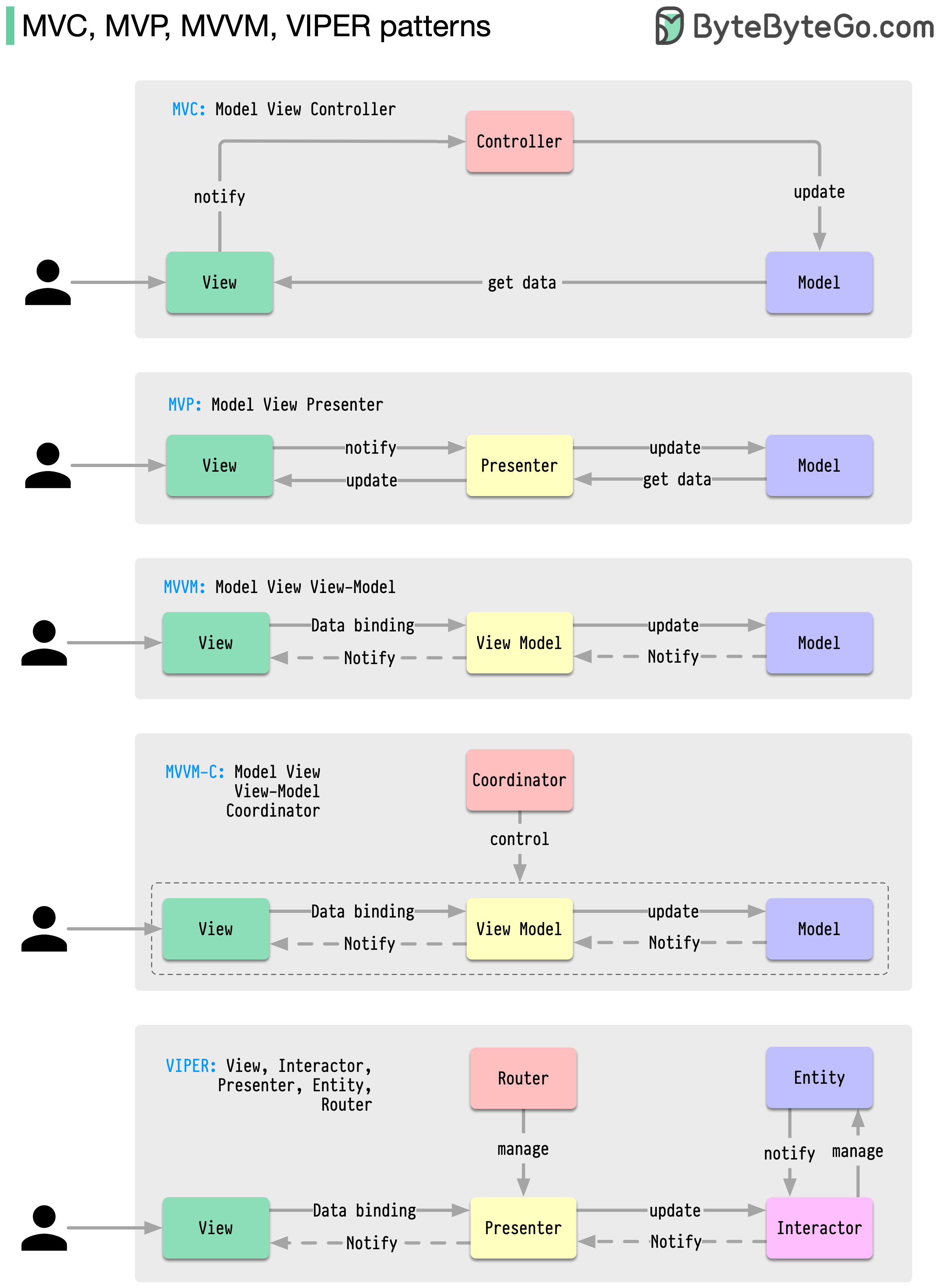
Patterns are reusable solutions to common design problems, resulting in a smoother, more efficient development process. They serve as blueprints for building better software structures. These are some of the most popular patterns:
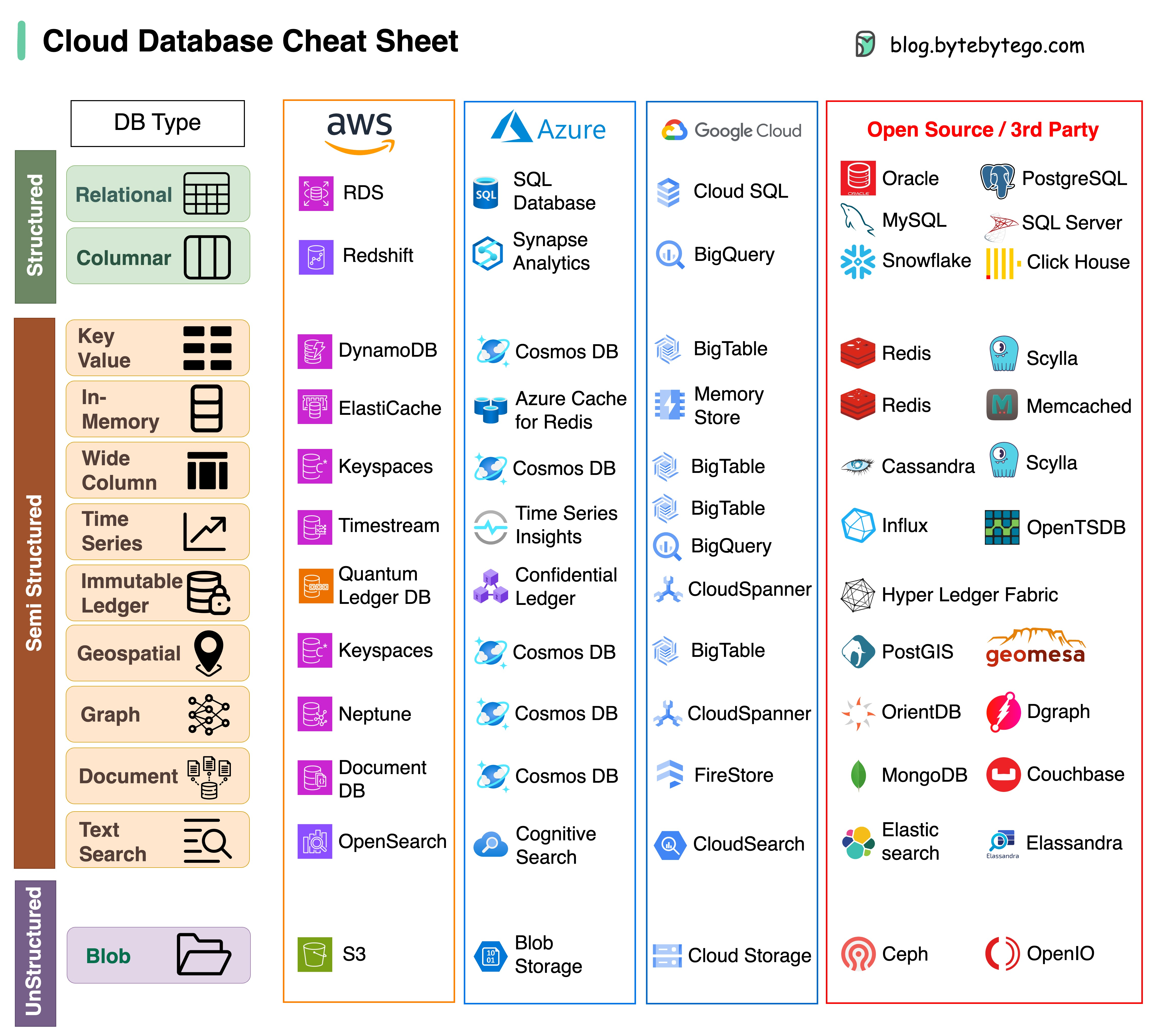
Choosing the right database for your project is a complex task. Many database options, each suited to distinct use cases, can quickly lead to decision fatigue.
We hope this cheat sheet provides high-level direction to pinpoint the right service that aligns with your project's needs and avoid potential pitfalls.
Note: Google has limited documentation for their database use cases. Even though we did our best to look at what was available and arrived at the best option, some of the entries may need to be more accurate.
The answer will vary depending on your use case. Data can be indexed in memory or on disk. Similarly, data formats vary, such as numbers, strings, geographic coordinates, etc. The system might be write-heavy or read-heavy. All of these factors affect your choice of database index format.
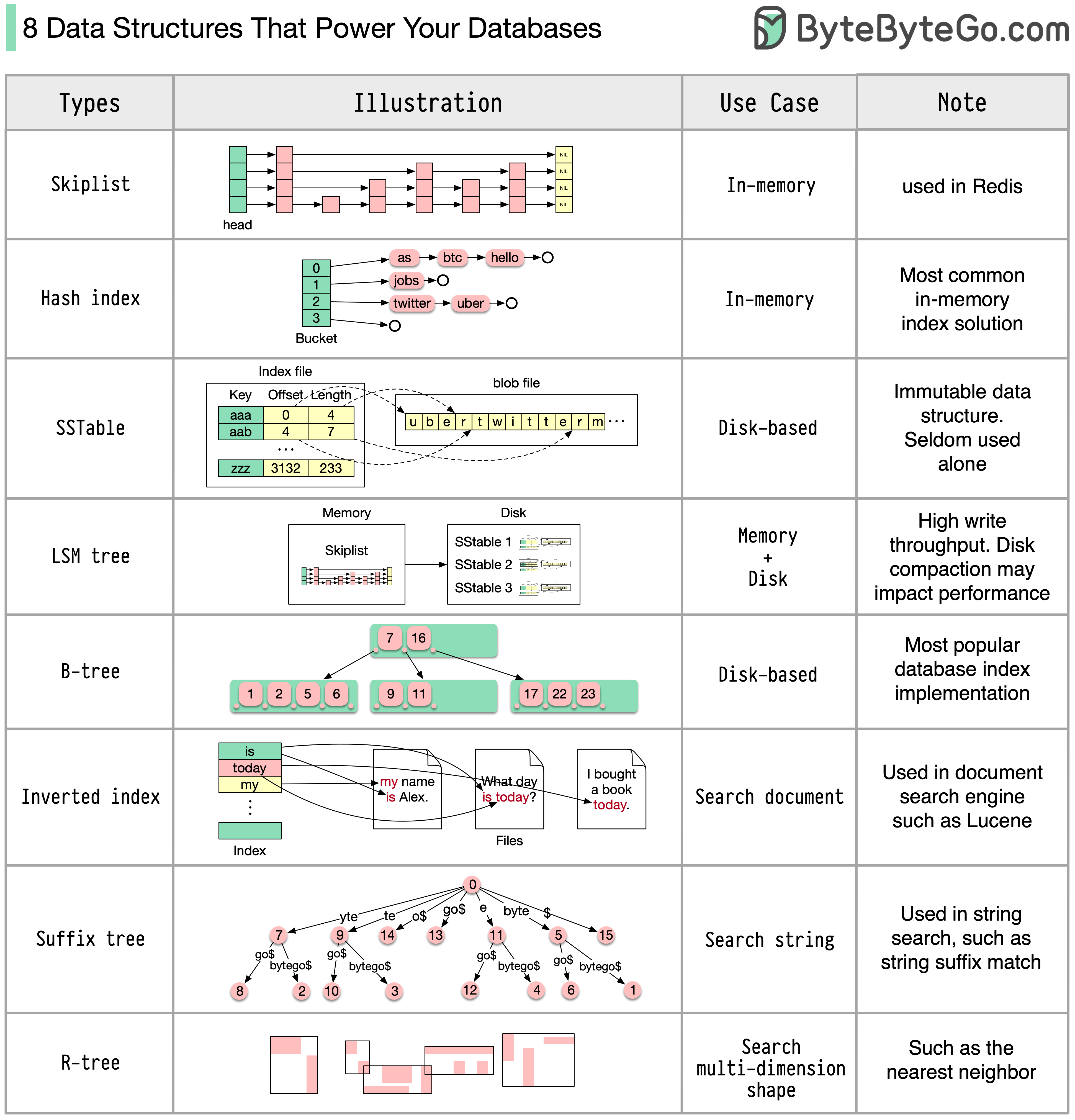
The following are some of the most popular data structures used for indexing data:
The diagram below shows the process. Note that the architectures for different databases are different, the diagram demonstrates some common designs.
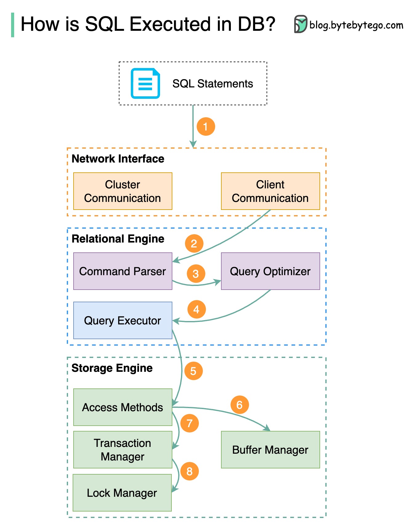
Step 1 - A SQL statement is sent to the database via a transport layer protocol (e.g.TCP).
Step 2 - The SQL statement is sent to the command parser, where it goes through syntactic and semantic analysis, and a query tree is generated afterward.
Step 3 - The query tree is sent to the optimizer. The optimizer creates an execution plan.
Step 4 - The execution plan is sent to the executor. The executor retrieves data from the execution.
Step 5 - Access methods provide the data fetching logic required for execution, retrieving data from the storage engine.
Step 6 - Access methods decide whether the SQL statement is read-only. If the query is read-only (SELECT statement), it is passed to the buffer manager for further processing. The buffer manager looks for the data in the cache or data files.
Step 7 - If the statement is an UPDATE or INSERT, it is passed to the transaction manager for further processing.
Step 8 - During a transaction, the data is in lock mode. This is guaranteed by the lock manager. It also ensures the transaction’s ACID properties.
The CAP theorem is one of the most famous terms in computer science, but I bet different developers have different understandings. Let’s examine what it is and why it can be confusing.
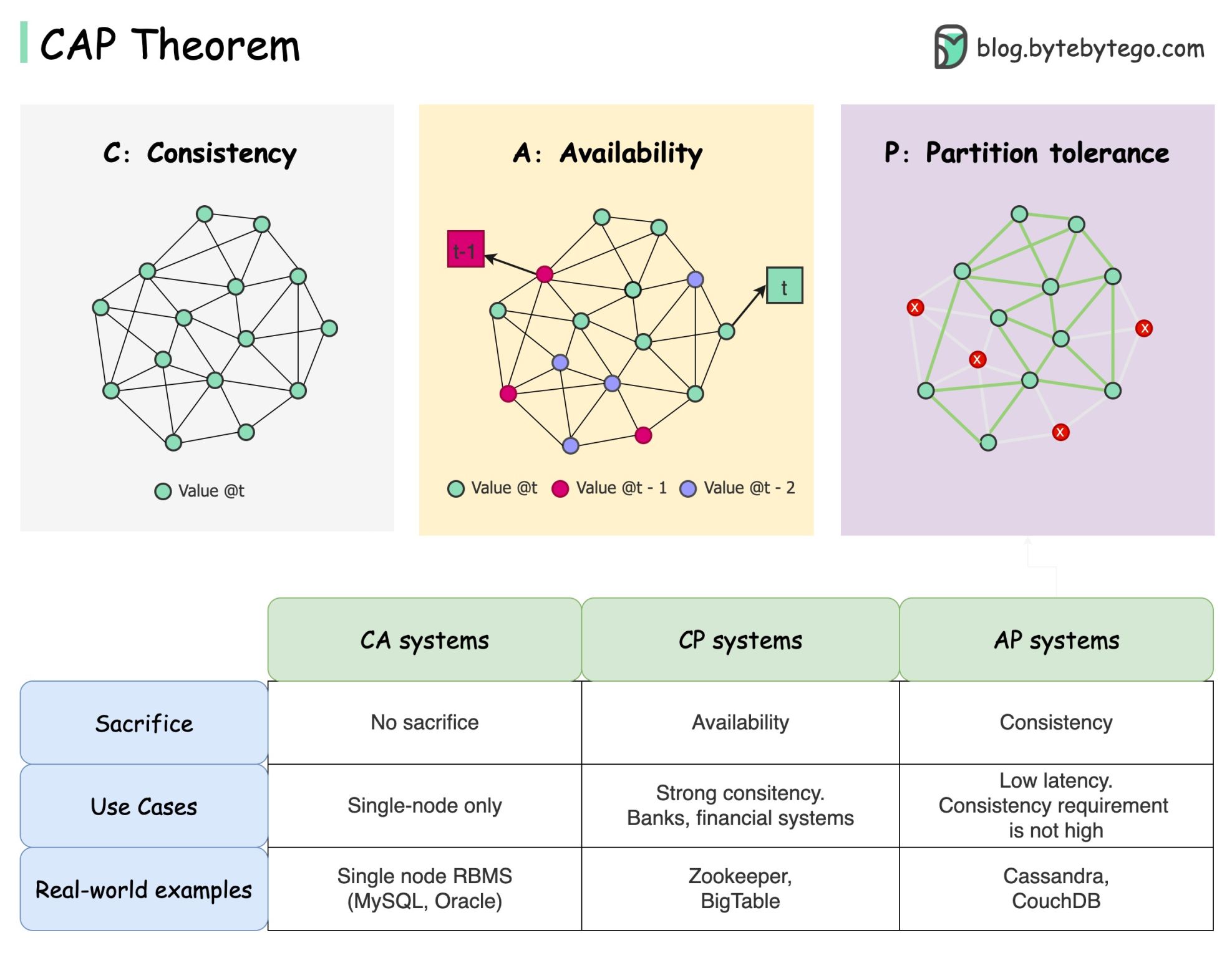
CAP theorem states that a distributed system can't provide more than two of these three guarantees simultaneously.
Consistency: consistency means all clients see the same data at the same time no matter which node they connect to.
Availability: availability means any client that requests data gets a response even if some of the nodes are down.
Partition Tolerance: a partition indicates a communication break between two nodes. Partition tolerance means the system continues to operate despite network partitions.
The “2 of 3” formulation can be useful, but this simplification could be misleading.
Picking a database is not easy. Justifying our choice purely based on the CAP theorem is not enough. For example, companies don't choose Cassandra for chat applications simply because it is an AP system. There is a list of good characteristics that make Cassandra a desirable option for storing chat messages. We need to dig deeper.
“CAP prohibits only a tiny part of the design space: perfect availability and consistency in the presence of partitions, which are rare”. Quoted from the paper: CAP Twelve Years Later: How the “Rules” Have Changed.
The theorem is about 100% availability and consistency. A more realistic discussion would be the trade-offs between latency and consistency when there is no network partition. See PACELC theorem for more details.
Is the CAP theorem actually useful?
I think it is still useful as it opens our minds to a set of tradeoff discussions, but it is only part of the story. We need to dig deeper when picking the right database.
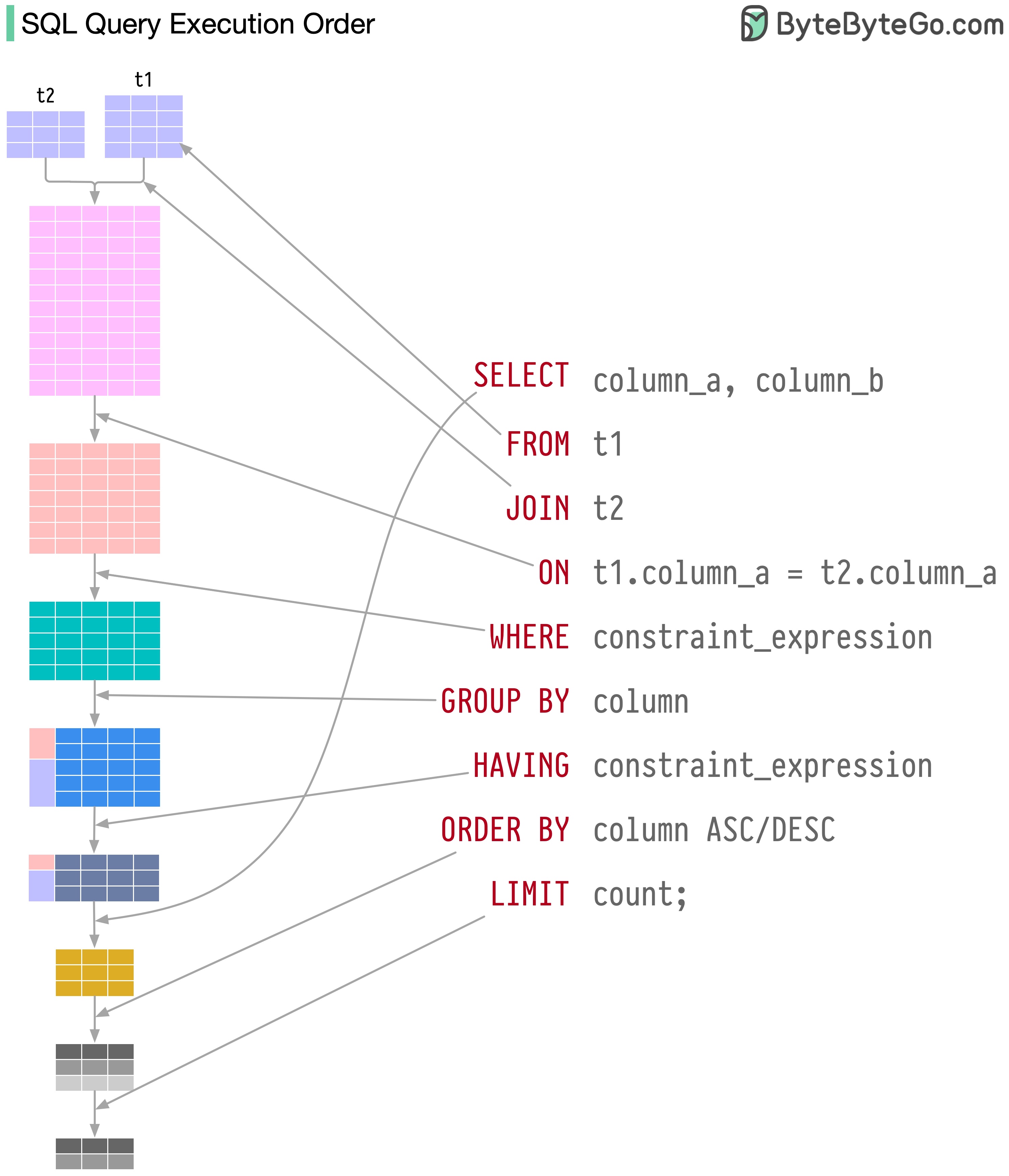
SQL statements are executed by the database system in several steps, including:
The execution of SQL is highly complex and involves many considerations, such as:
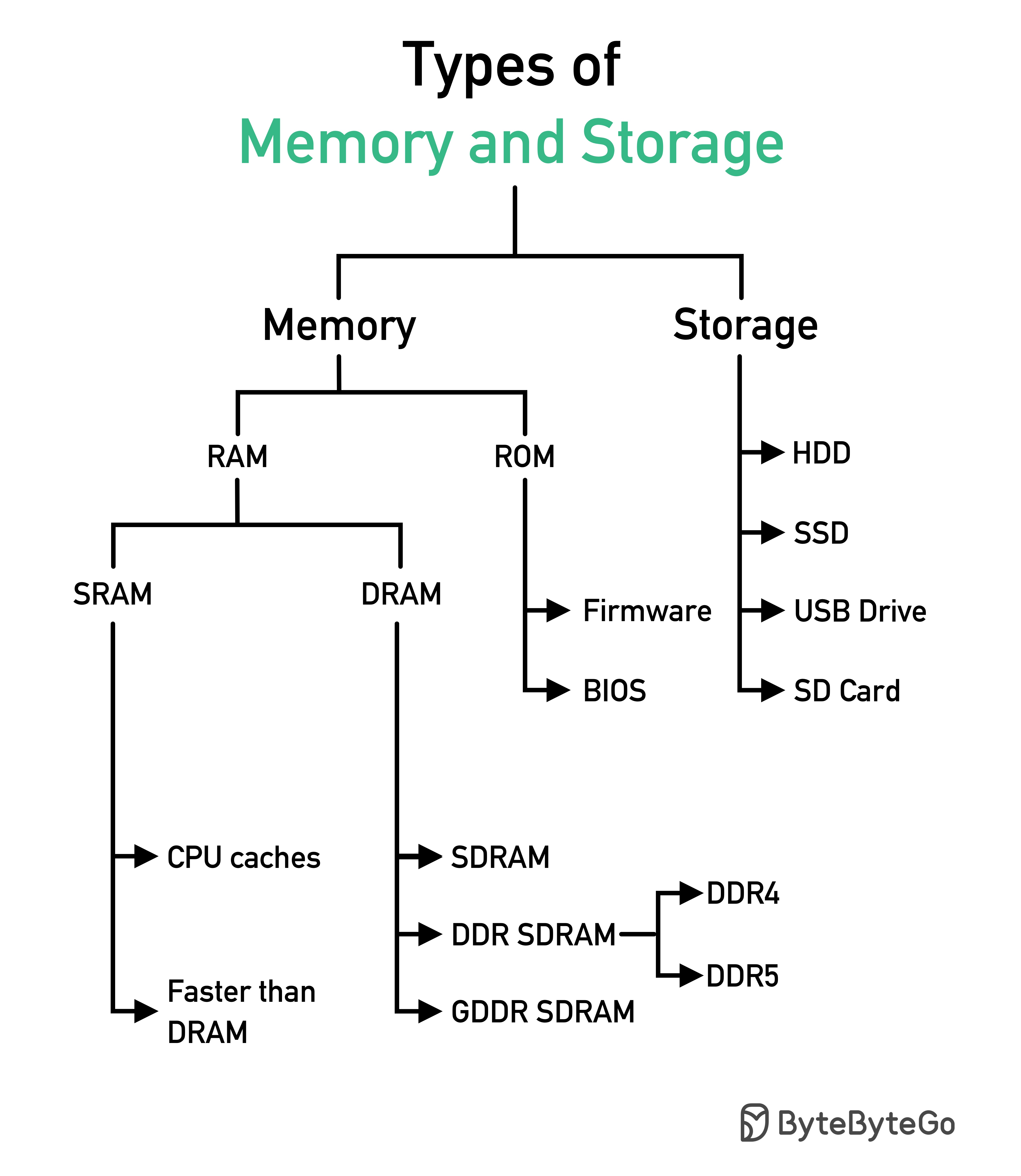
In 1986, SQL (Structured Query Language) became a standard. Over the next 40 years, it became the dominant language for relational database management systems. Reading the latest standard (ANSI SQL 2016) can be time-consuming. How can I learn it?
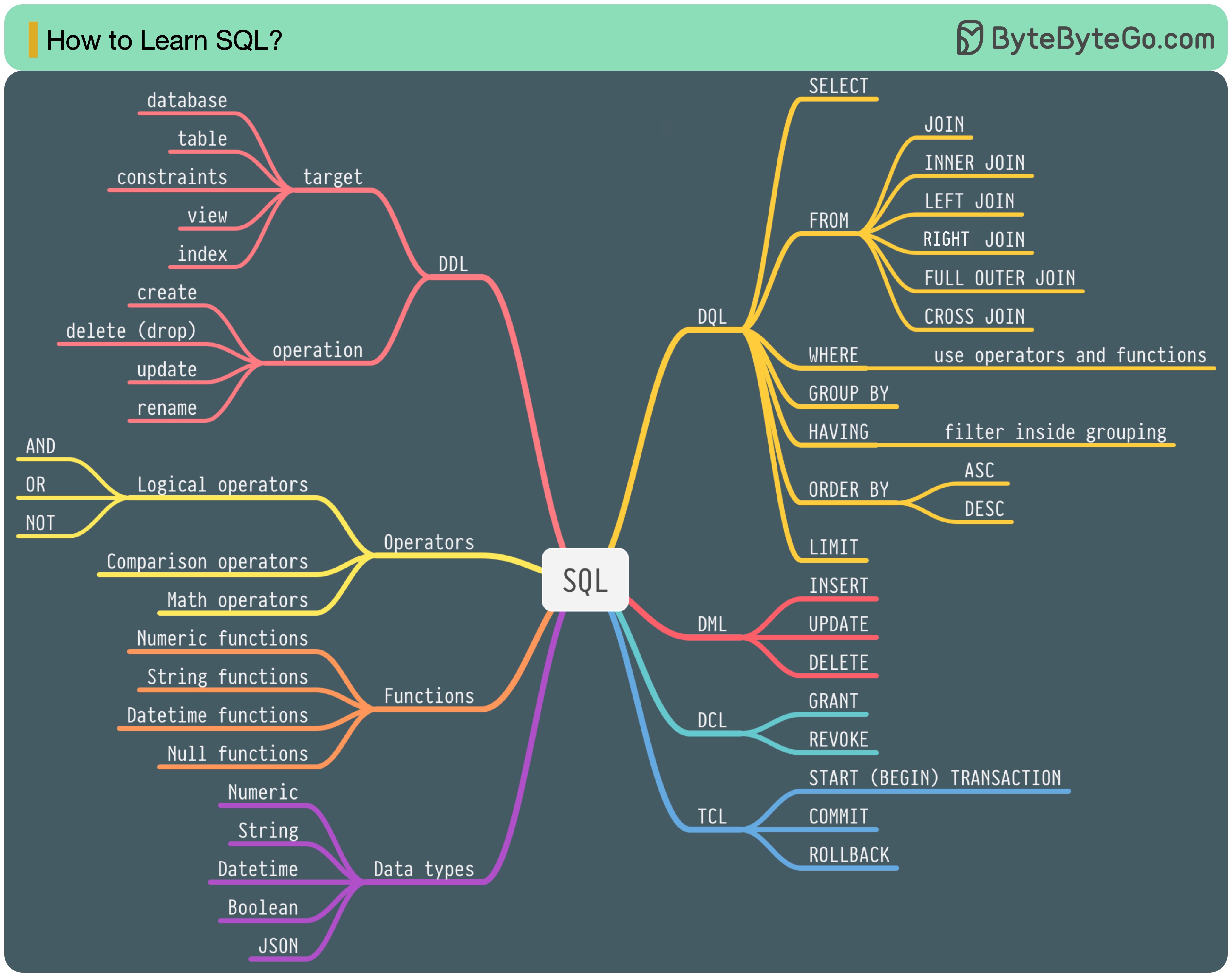
There are 5 components of the SQL language:
For a backend engineer, you may need to know most of it. As a data analyst, you may need to have a good understanding of DQL. Select the topics that are most relevant to you.
This diagram illustrates where we cache data in a typical architecture.
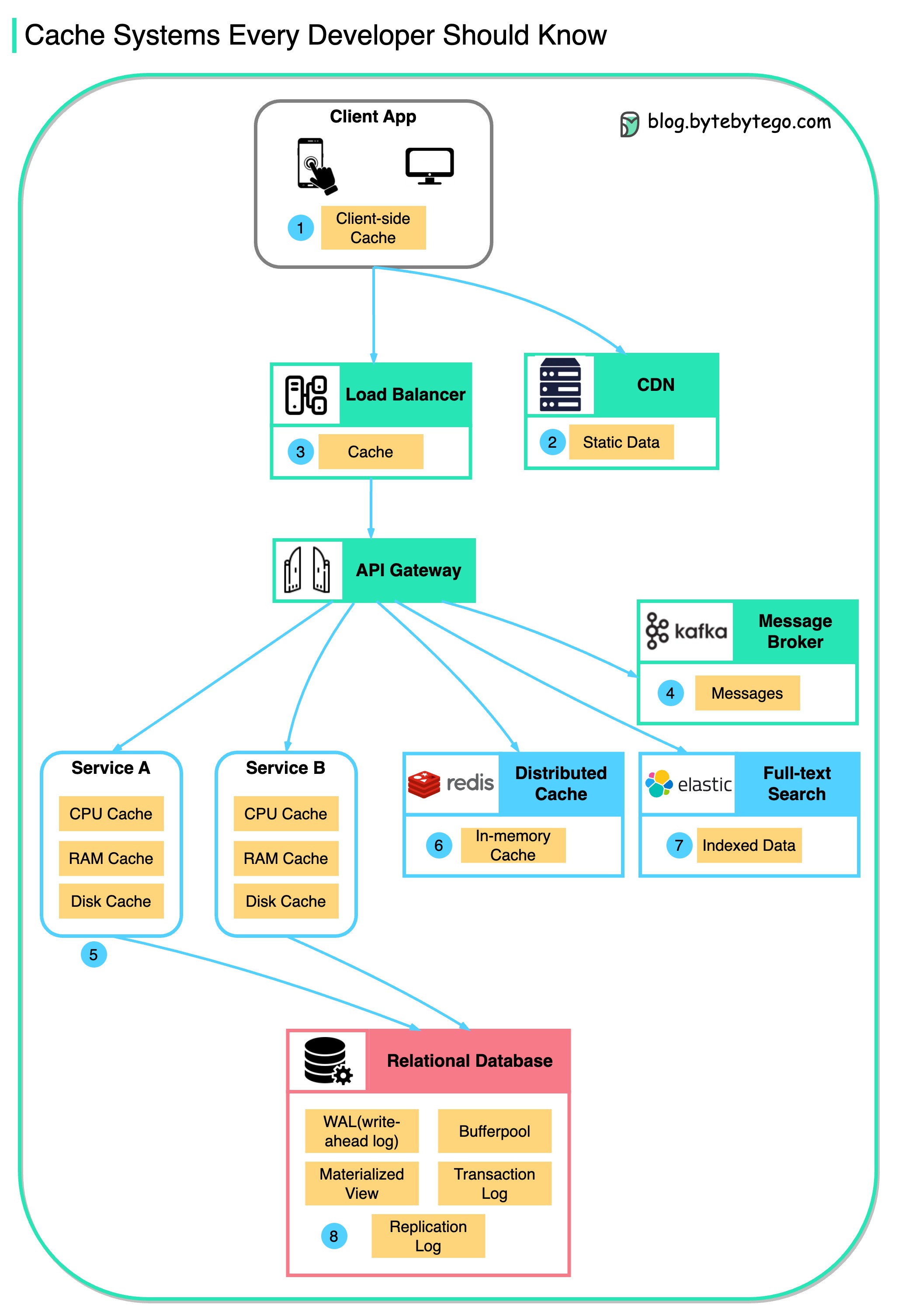
There are multiple layers along the flow.
There are 3 main reasons as shown in the diagram below.
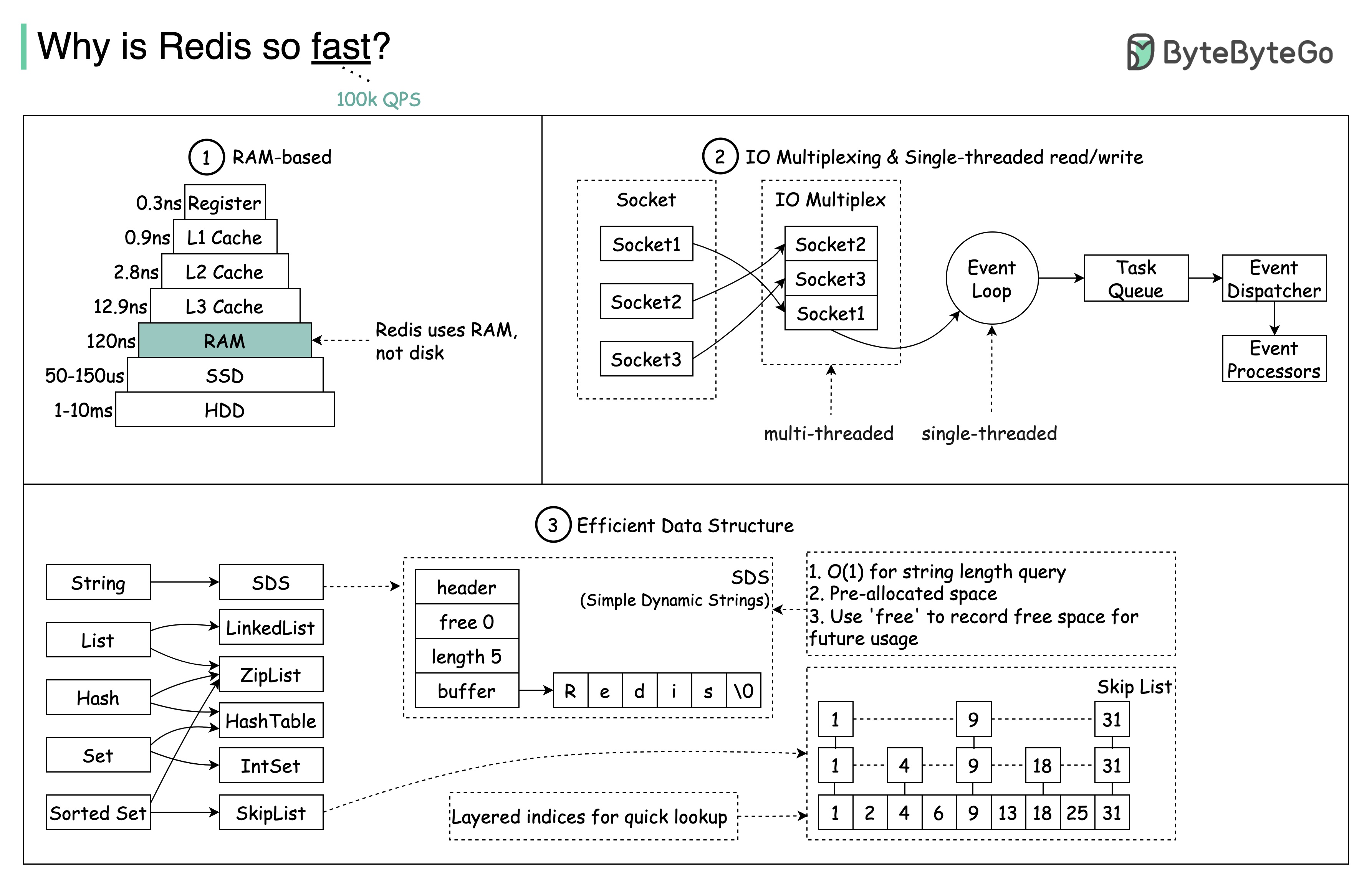
Question: Another popular in-memory store is Memcached. Do you know the differences between Redis and Memcached?
You might have noticed the style of this diagram is different from my previous posts. Please let me know which one you prefer.
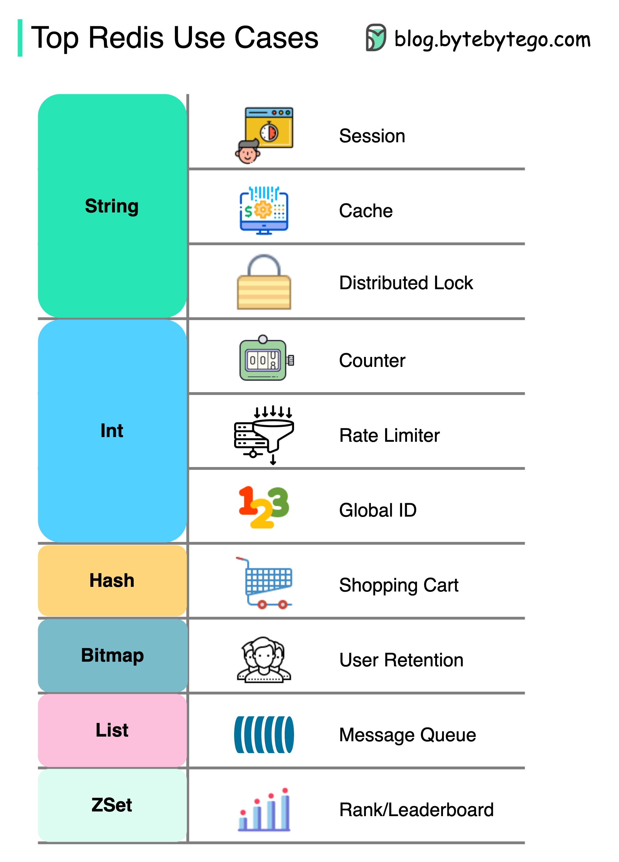
There is more to Redis than just caching.
Redis can be used in a variety of scenarios as shown in the diagram.
Session
We can use Redis to share user session data among different services.
Cache
We can use Redis to cache objects or pages, especially for hotspot data.
Distributed lock
We can use a Redis string to acquire locks among distributed services.
Counter
We can count how many likes or how many reads for articles.
Rate limiter
We can apply a rate limiter for certain user IPs.
Global ID generator
We can use Redis Int for global ID.
Shopping cart
We can use Redis Hash to represent key-value pairs in a shopping cart.
Calculate user retention
We can use Bitmap to represent the user login daily and calculate user retention.
Message queue
We can use List for a message queue.
Ranking
We can use ZSet to sort the articles.
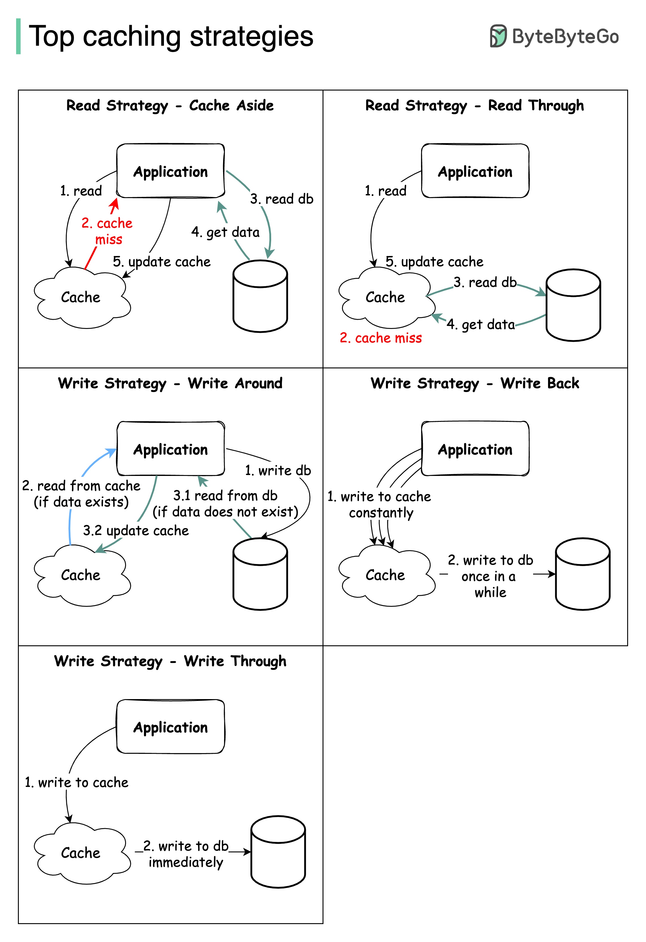
Designing large-scale systems usually requires careful consideration of caching. Below are five caching strategies that are frequently utilized.
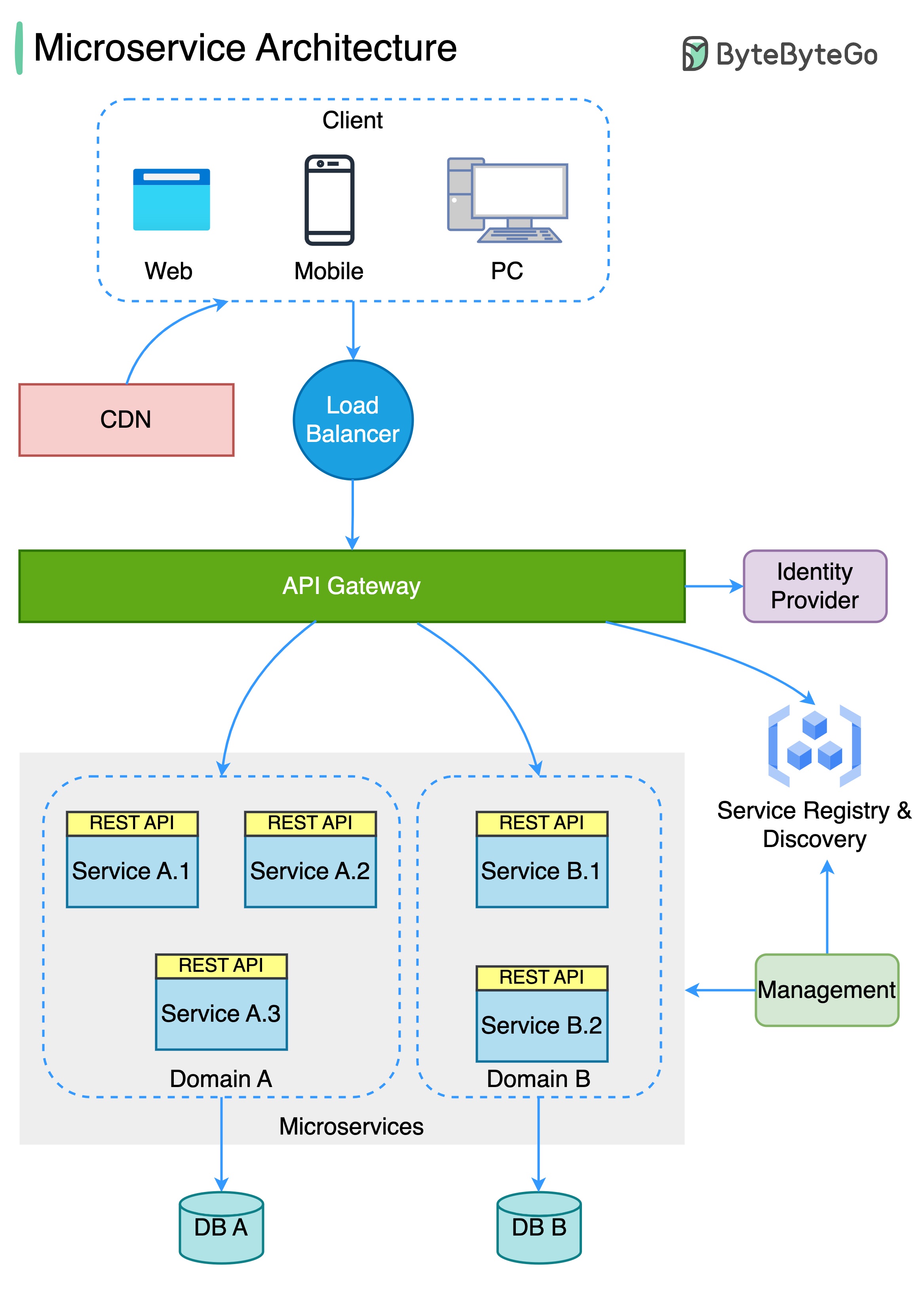
The diagram below shows a typical microservice architecture.
Benefits of microservices:
A picture is worth a thousand words: 9 best practices for developing microservices.
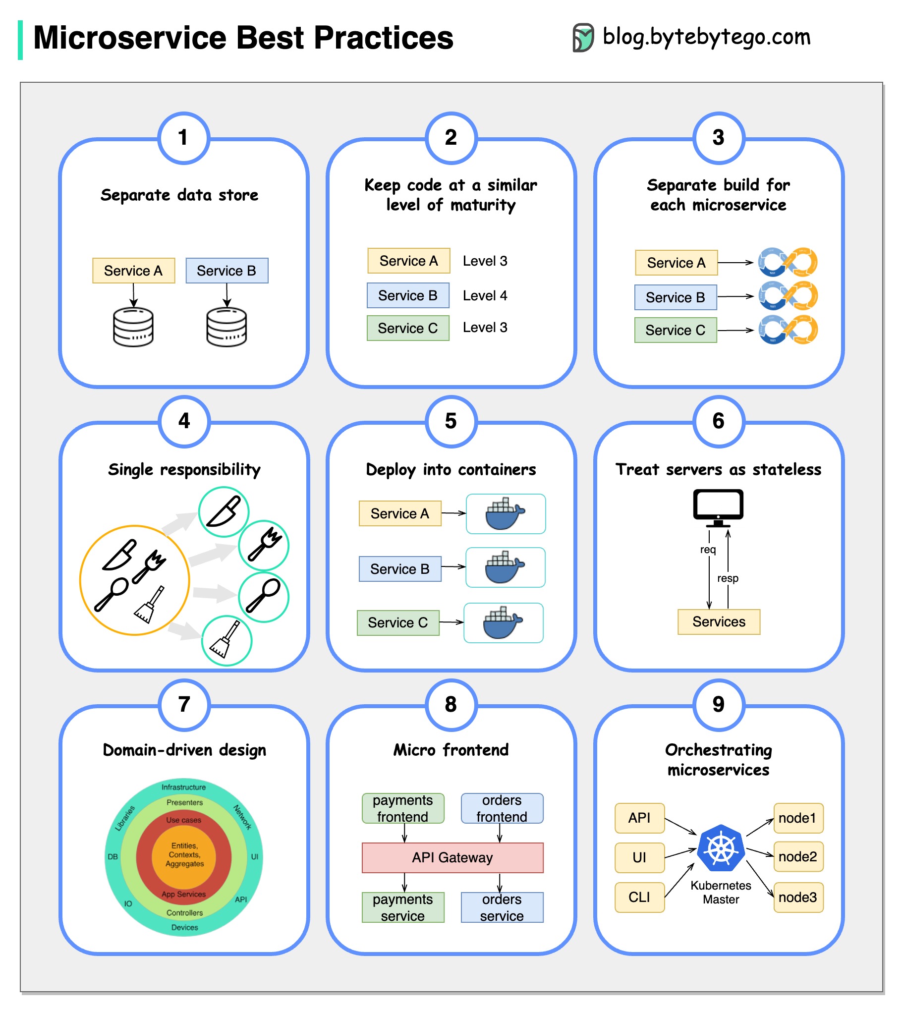
When we develop microservices, we need to follow the following best practices:
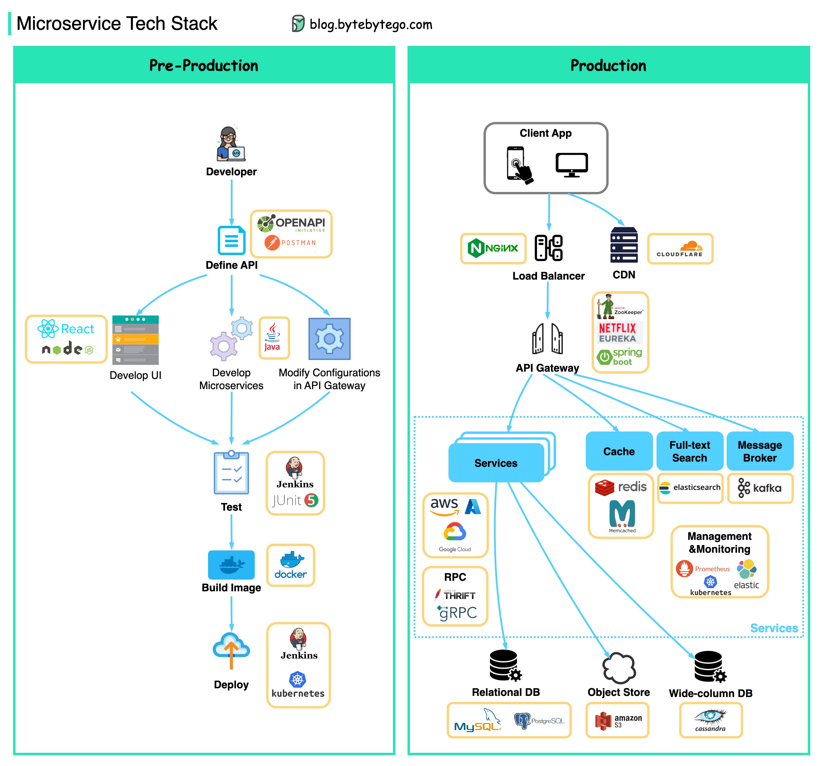
Below you will find a diagram showing the microservice tech stack, both for the development phase and for production.
There are many design decisions that contributed to Kafka’s performance. In this post, we’ll focus on two. We think these two carried the most weight.
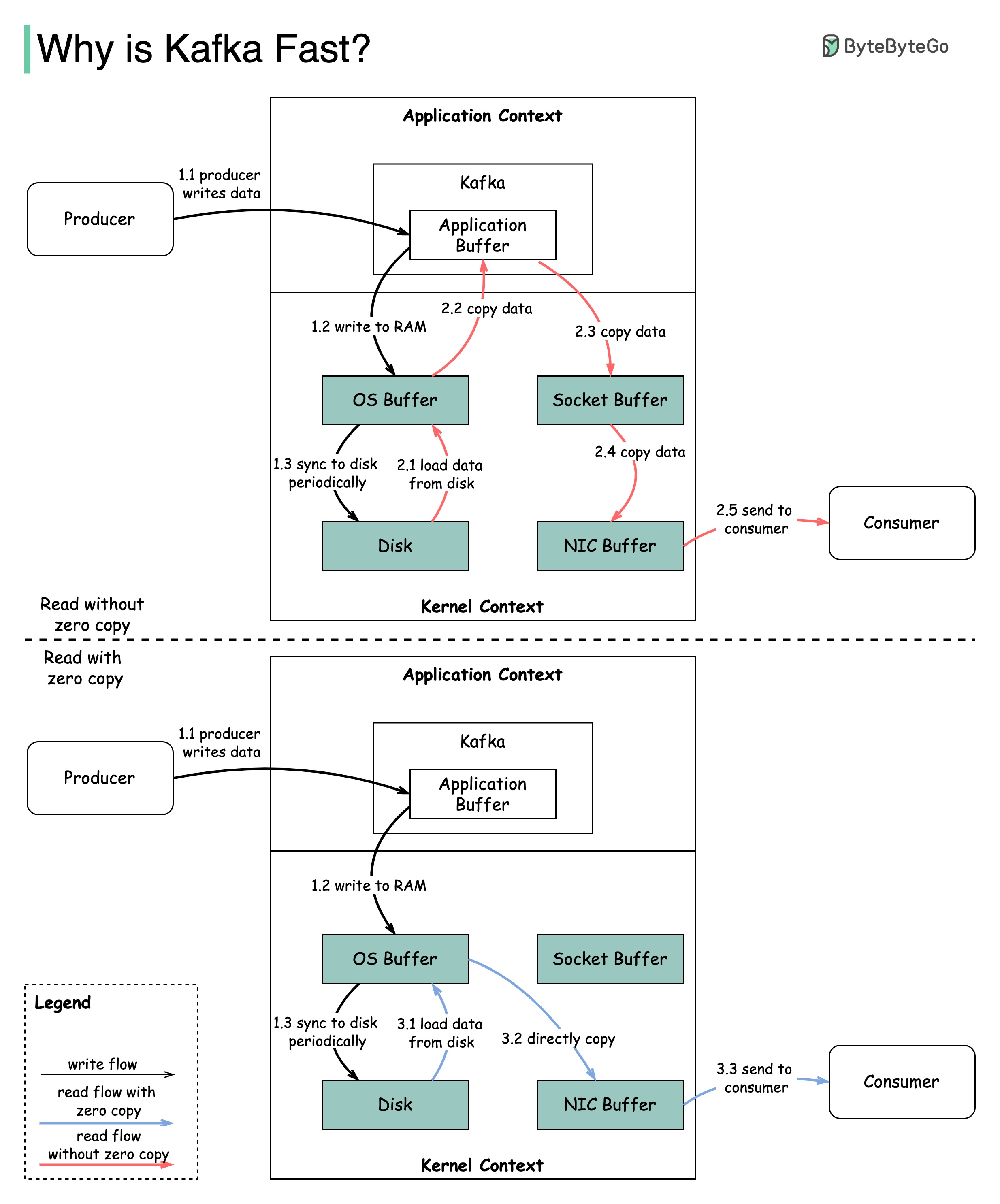
The diagram illustrates how the data is transmitted between producer and consumer, and what zero-copy means.
2.1 The data is loaded from disk to OS cache
2.2 The data is copied from OS cache to Kafka application
2.3 Kafka application copies the data into the socket buffer
2.4 The data is copied from socket buffer to network card
2.5 The network card sends data out to the consumer
3.1: The data is loaded from disk to OS cache 3.2 OS cache directly copies the data to the network card via sendfile() command 3.3 The network card sends data out to the consumer
Zero copy is a shortcut to save the multiple data copies between application context and kernel context.
The diagram below shows the economics of the credit card payment flow.
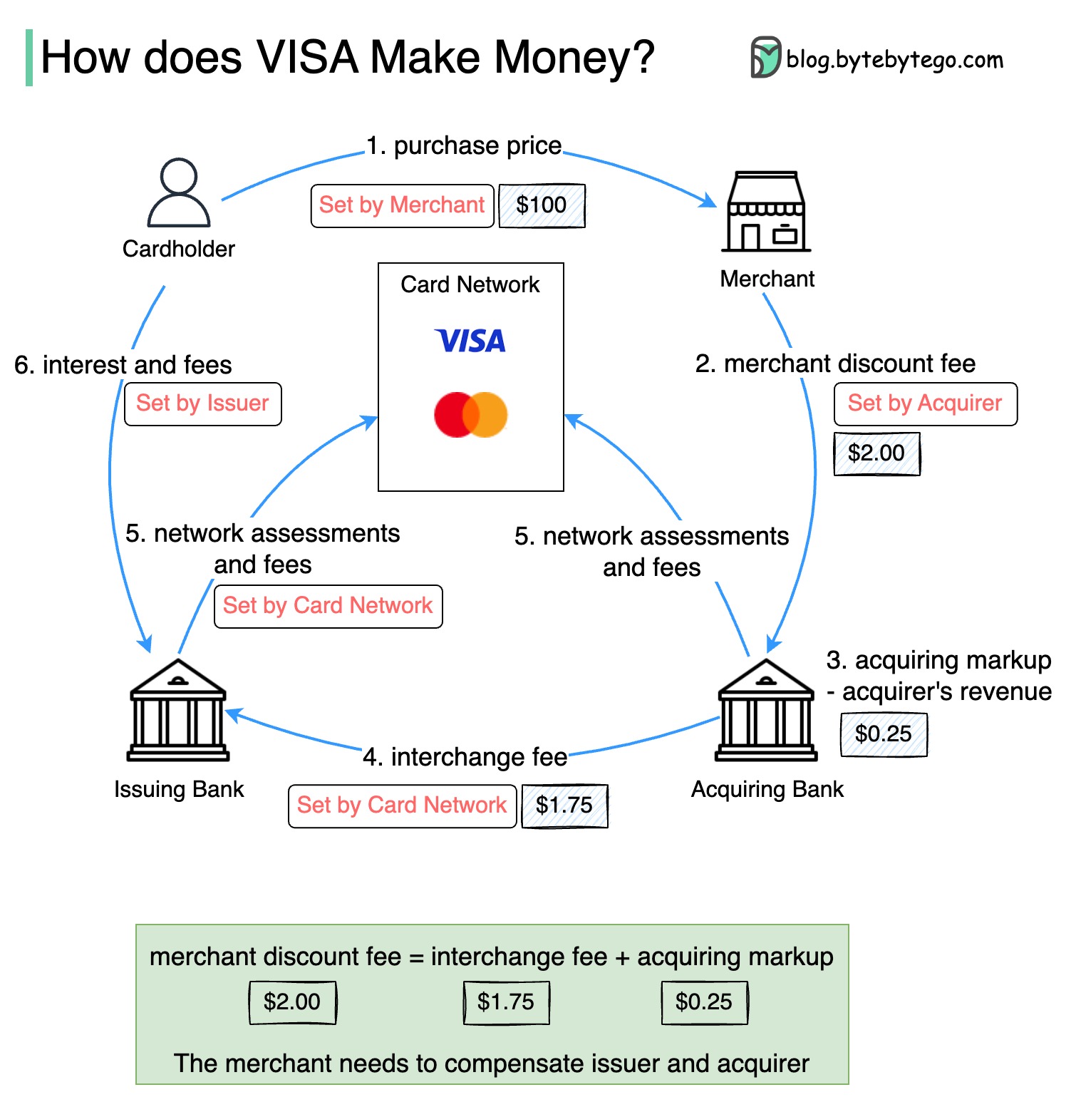
1. The cardholder pays a merchant $100 to buy a product.
2. The merchant benefits from the use of the credit card with higher sales volume and needs to compensate the issuer and the card network for providing the payment service. The acquiring bank sets a fee with the merchant, called the “merchant discount fee.”
3 - 4. The acquiring bank keeps $0.25 as the acquiring markup, and $1.75 is paid to the issuing bank as the interchange fee. The merchant discount fee should cover the interchange fee.
The interchange fee is set by the card network because it is less efficient for each issuing bank to negotiate fees with each merchant.
5. The card network sets up the network assessments and fees with each bank, which pays the card network for its services every month. For example, VISA charges a 0.11% assessment, plus a $0.0195 usage fee, for every swipe.
6. The cardholder pays the issuing bank for its services.
Why should the issuing bank be compensated?
VISA, Mastercard, and American Express act as card networks for the clearing and settling of funds. The card acquiring bank and the card issuing bank can be – and often are – different. If banks were to settle transactions one by one without an intermediary, each bank would have to settle the transactions with all the other banks. This is quite inefficient.
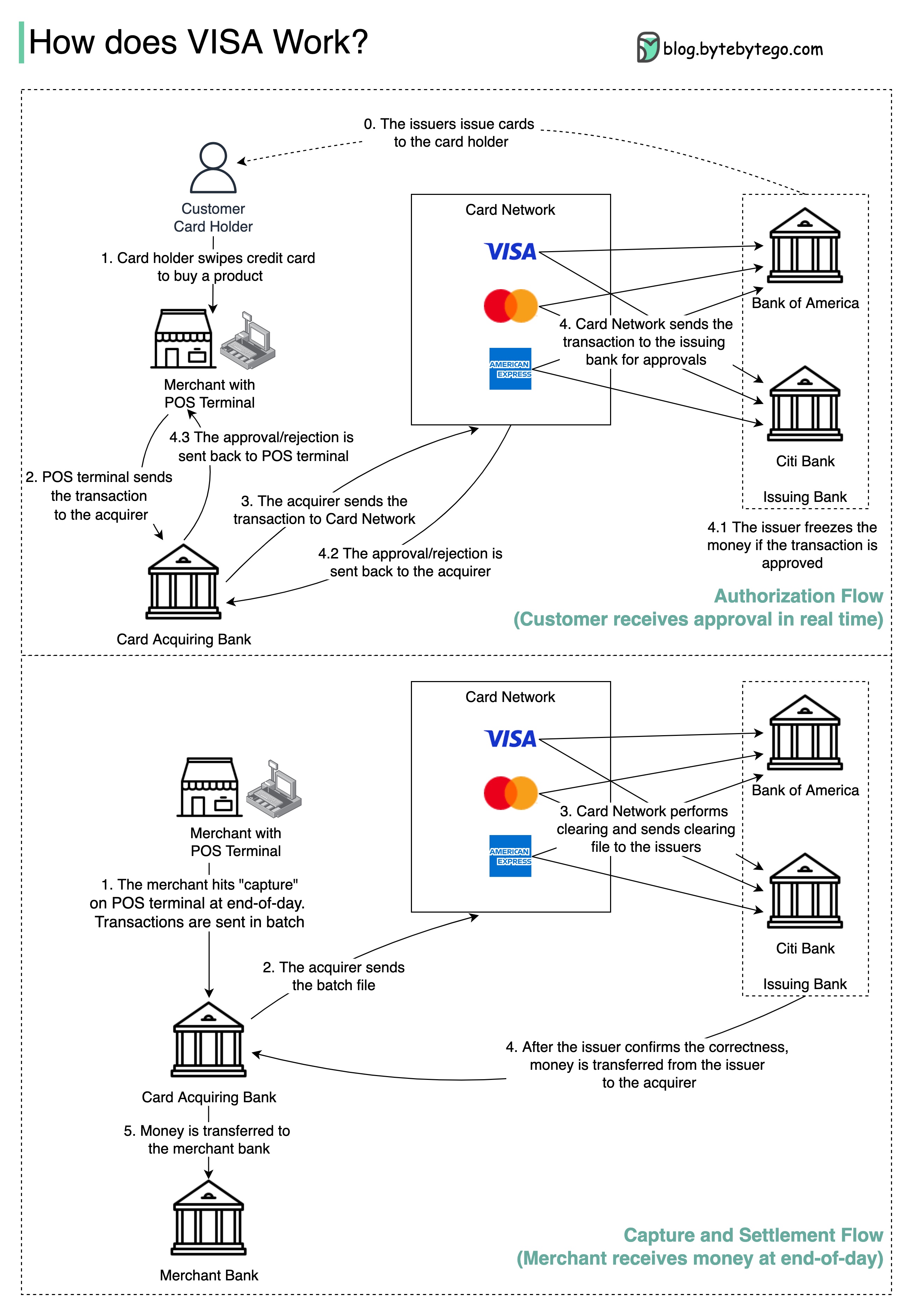
The diagram below shows VISA’s role in the credit card payment process. There are two flows involved. Authorization flow happens when the customer swipes the credit card. Capture and settlement flow happens when the merchant wants to get the money at the end of the day.
Step 0: The card issuing bank issues credit cards to its customers.
Step 1: The cardholder wants to buy a product and swipes the credit card at the Point of Sale (POS) terminal in the merchant’s shop.
Step 2: The POS terminal sends the transaction to the acquiring bank, which has provided the POS terminal.
Steps 3 and 4: The acquiring bank sends the transaction to the card network, also called the card scheme. The card network sends the transaction to the issuing bank for approval.
Steps 4.1, 4.2 and 4.3: The issuing bank freezes the money if the transaction is approved. The approval or rejection is sent back to the acquirer, as well as the POS terminal.
Steps 1 and 2: The merchant wants to collect the money at the end of the day, so they hit ”capture” on the POS terminal. The transactions are sent to the acquirer in batch. The acquirer sends the batch file with transactions to the card network.
Step 3: The card network performs clearing for the transactions collected from different acquirers, and sends the clearing files to different issuing banks.
Step 4: The issuing banks confirm the correctness of the clearing files, and transfer money to the relevant acquiring banks.
Step 5: The acquiring bank then transfers money to the merchant’s bank.
Step 4: The card network clears up the transactions from different acquiring banks. Clearing is a process in which mutual offset transactions are netted, so the number of total transactions is reduced.
In the process, the card network takes on the burden of talking to each bank and receives service fees in return.
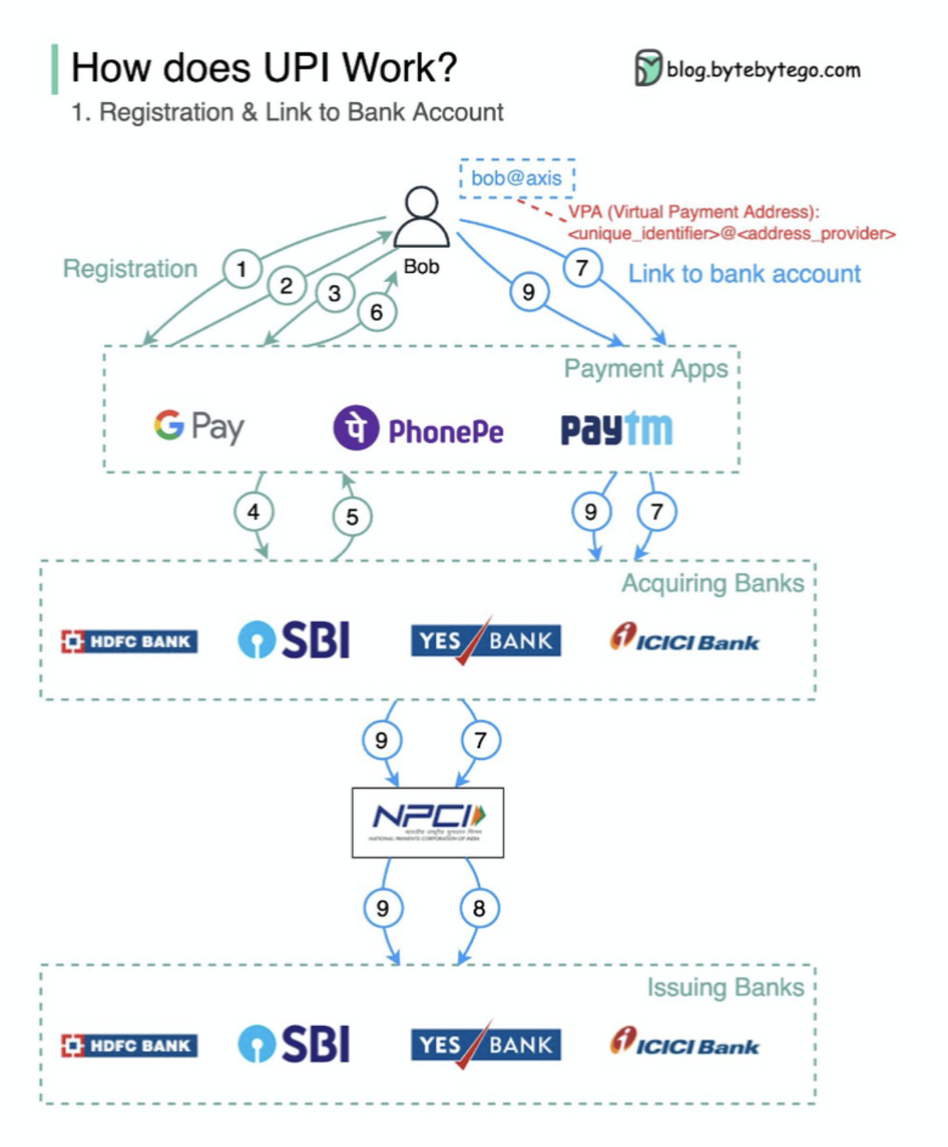
What’s UPI? UPI is an instant real-time payment system developed by the National Payments Corporation of India.
It accounts for 60% of digital retail transactions in India today.
UPI = payment markup language + standard for interoperable payments
The concepts of DevOps, SRE, and Platform Engineering have emerged at different times and have been developed by various individuals and organizations.
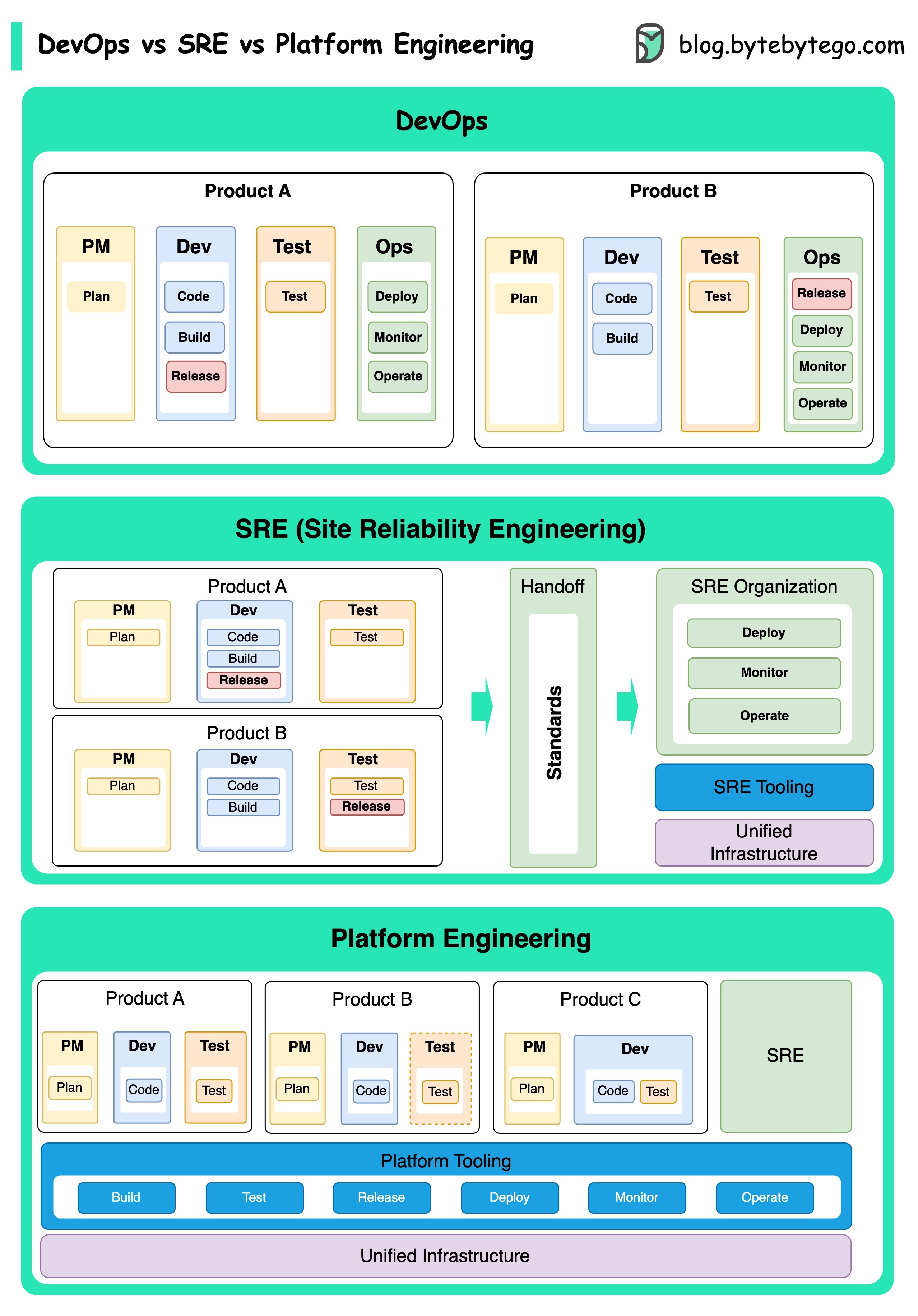
DevOps as a concept was introduced in 2009 by Patrick Debois and Andrew Shafer at the Agile conference. They sought to bridge the gap between software development and operations by promoting a collaborative culture and shared responsibility for the entire software development lifecycle.
SRE, or Site Reliability Engineering, was pioneered by Google in the early 2000s to address operational challenges in managing large-scale, complex systems. Google developed SRE practices and tools, such as the Borg cluster management system and the Monarch monitoring system, to improve the reliability and efficiency of their services.
Platform Engineering is a more recent concept, building on the foundation of SRE engineering. The precise origins of Platform Engineering are less clear, but it is generally understood to be an extension of the DevOps and SRE practices, with a focus on delivering a comprehensive platform for product development that supports the entire business perspective.
It's worth noting that while these concepts emerged at different times. They are all related to the broader trend of improving collaboration, automation, and efficiency in software development and operations.
K8s is a container orchestration system. It is used for container deployment and management. Its design is greatly impacted by Google’s internal system Borg.
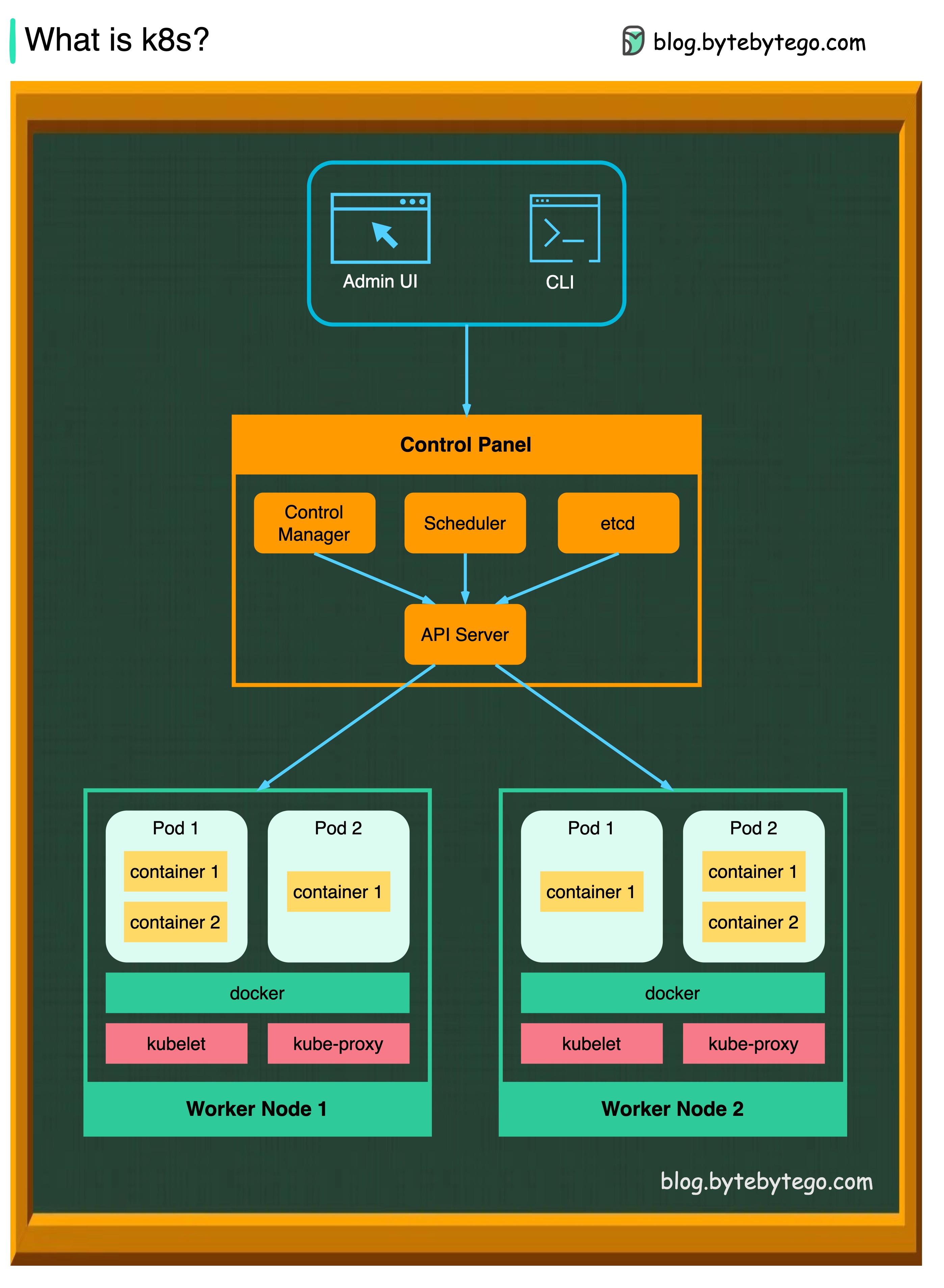
A k8s cluster consists of a set of worker machines, called nodes, that run containerized applications. Every cluster has at least one worker node.
The worker node(s) host the Pods that are the components of the application workload. The control plane manages the worker nodes and the Pods in the cluster. In production environments, the control plane usually runs across multiple computers, and a cluster usually runs multiple nodes, providing fault tolerance and high availability.
API Server
The API server talks to all the components in the k8s cluster. All the operations on pods are executed by talking to the API server.
Scheduler
The scheduler watches pod workloads and assigns loads on newly created pods.
Controller Manager
The controller manager runs the controllers, including Node Controller, Job Controller, EndpointSlice Controller, and ServiceAccount Controller.
Etcd
etcd is a key-value store used as Kubernetes' backing store for all cluster data.
Pods
A pod is a group of containers and is the smallest unit that k8s administers. Pods have a single IP address applied to every container within the pod.
Kubelet
An agent that runs on each node in the cluster. It ensures containers are running in a Pod.
Kube Proxy
Kube-proxy is a network proxy that runs on each node in your cluster. It routes traffic coming into a node from the service. It forwards requests for work to the correct containers.

What is Docker ?
Docker is an open-source platform that allows you to package, distribute, and run applications in isolated containers. It focuses on containerization, providing lightweight environments that encapsulate applications and their dependencies.
What is Kubernetes ?
Kubernetes, often referred to as K8s, is an open-source container orchestration platform. It provides a framework for automating the deployment, scaling, and management of containerized applications across a cluster of nodes.
How are both different from each other ?
Docker: Docker operates at the individual container level on a single operating system host.
You must manually manage each host and setting up networks, security policies, and storage for multiple related containers can be complex.
Kubernetes: Kubernetes operates at the cluster level. It manages multiple containerized applications across multiple hosts, providing automation for tasks like load balancing, scaling, and ensuring the desired state of applications.
In short, Docker focuses on containerization and running containers on individual hosts, while Kubernetes specializes in managing and orchestrating containers at scale across a cluster of hosts.
The diagram below shows the architecture of Docker and how it works when we run “docker build”, “docker pull” and “docker run”.
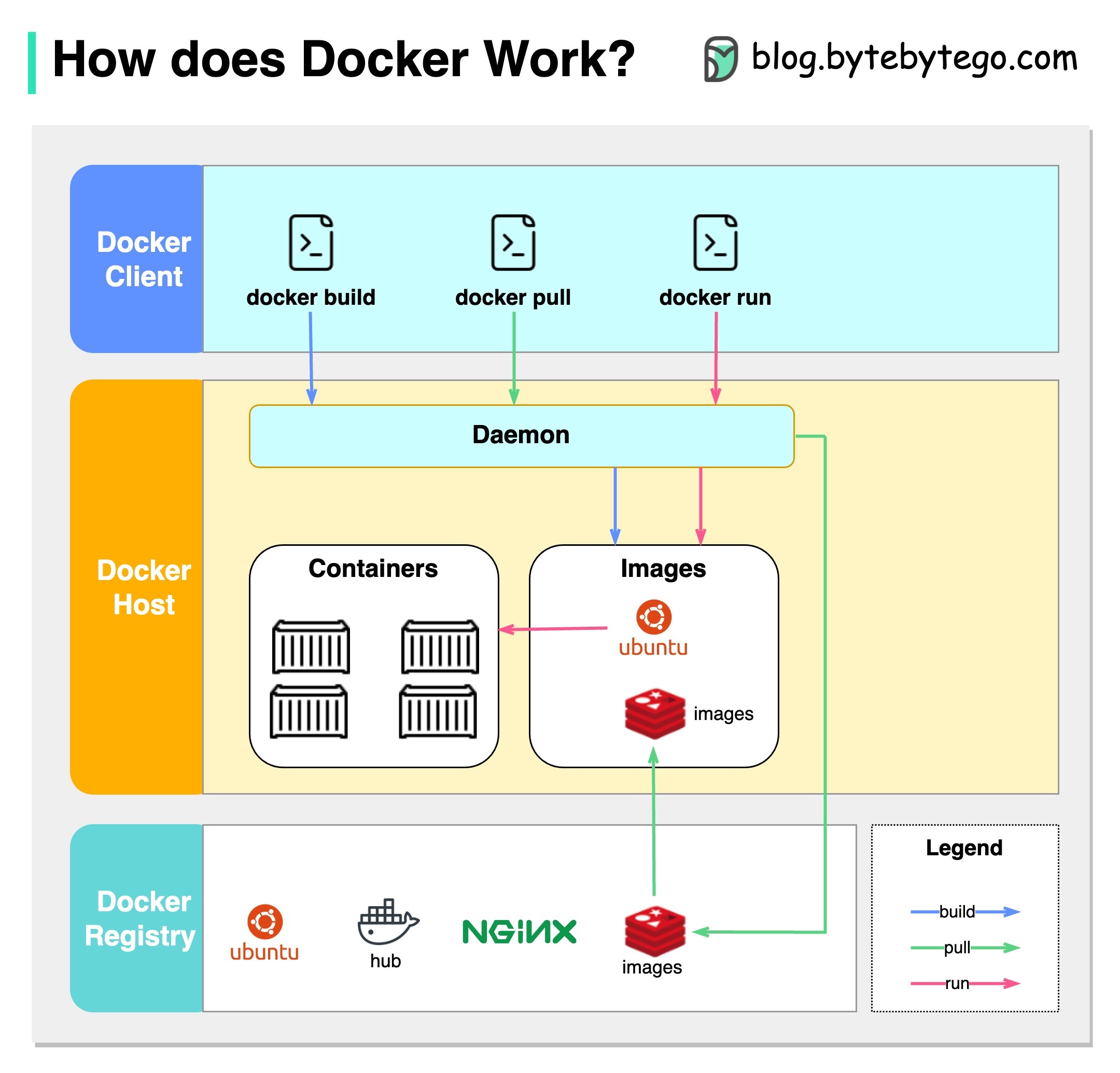
There are 3 components in Docker architecture:
Docker client
The docker client talks to the Docker daemon.
Docker host
The Docker daemon listens for Docker API requests and manages Docker objects such as images, containers, networks, and volumes.
Docker registry
A Docker registry stores Docker images. Docker Hub is a public registry that anyone can use.
Let’s take the “docker run” command as an example.
To begin with, it's essential to identify where our code is stored. The common assumption is that there are only two locations - one on a remote server like Github and the other on our local machine. However, this isn't entirely accurate. Git maintains three local storages on our machine, which means that our code can be found in four places:
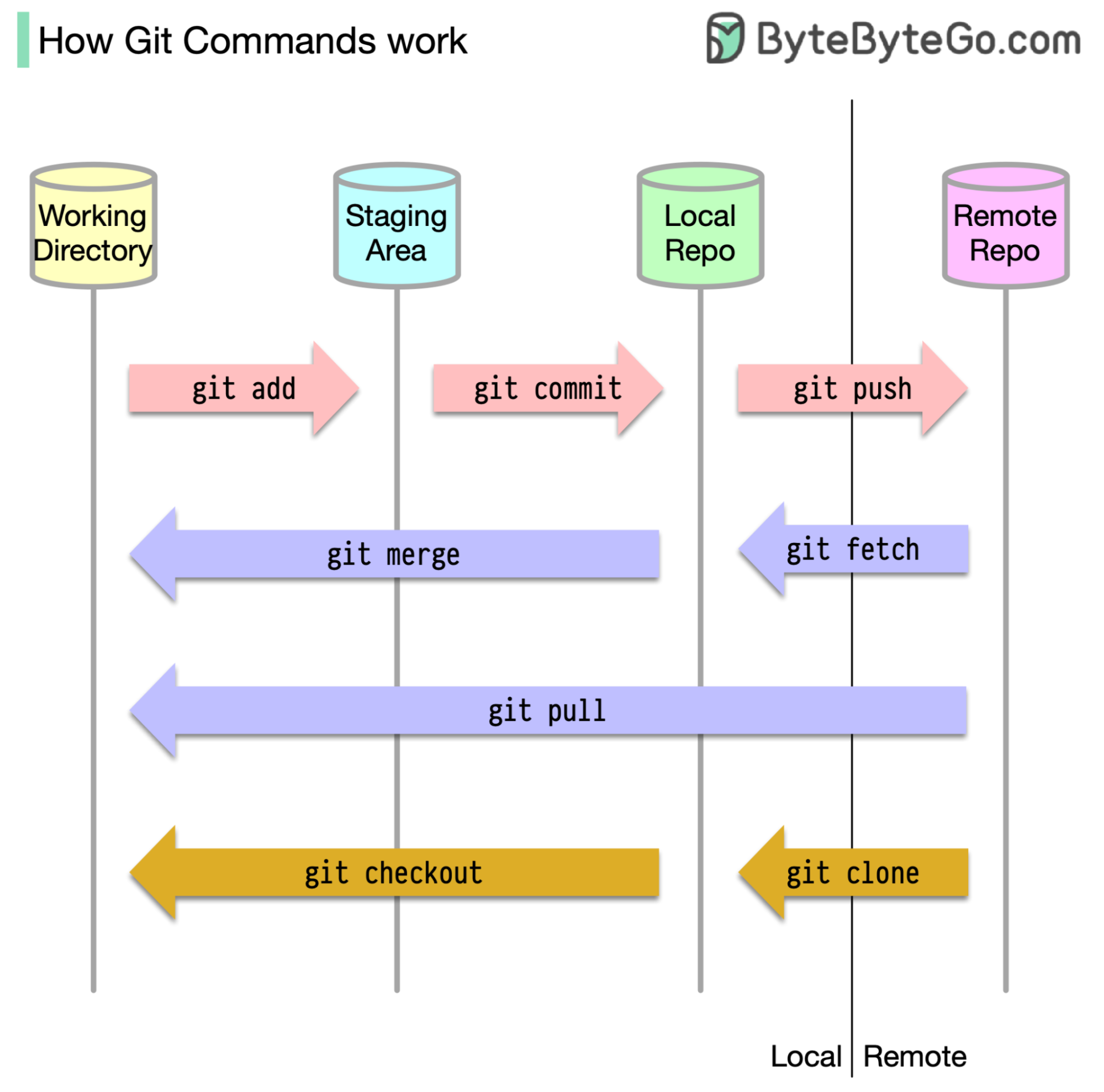
Most Git commands primarily move files between these four locations.
The diagram below shows the Git workflow.
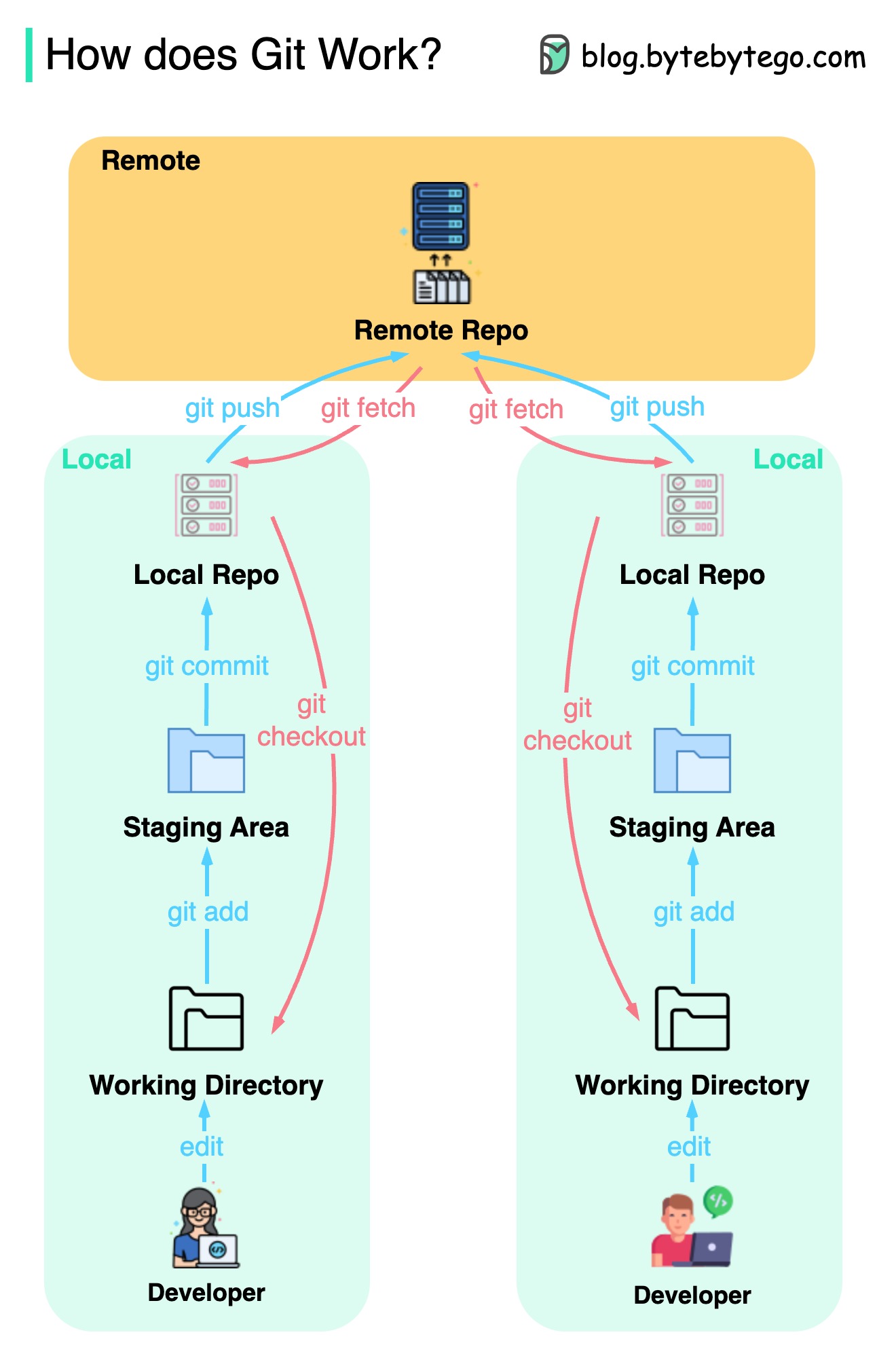
Git is a distributed version control system.
Every developer maintains a local copy of the main repository and edits and commits to the local copy.
The commit is very fast because the operation doesn’t interact with the remote repository.
If the remote repository crashes, the files can be recovered from the local repositories.
What are the differences?


