fbcp ili9341
1.0.0
La era de FBCP-ILI9341 ha llegado a su fin. FBCP-ILI9341 se construyó en la parte superior de la API DISPMANX Videocore de Raspberry Pi.
Sin embargo, esta API ha sido desaprobada por la Fundación Raspberry Pi desde hace un tiempo, y finalmente obsoleta (= no disponible) en Raspberry Pi 5 y en adelante.
Las distribuciones posteriores de Raspberry Pi ya no tienen DispManx activa por defecto incluso para PI0-PI4, sino que Raspberry Pi se ha trasladado a la nueva pila de compositor de controladores KMS, que tiene una abstracción diferente para integrar los controladores de pantalla SPI. Otras personas están desarrollando controladores de pantalla SPI para el PI que son compatibles con la pila KMS. Dirígete a este hilo del foro Raspberry Pi para obtener más información.
Este repositorio es bueno para ser considerado archivado/rancio, aunque no lo estoy archivando archivado usando la función GitHub, ya que esa característica aparentemente también haría que el rastreador de problemas sea de solo lectura. Siéntase libre de continuar discutiendo temas en el rastreador.
Este repositorio implementa un controlador para ciertas pantallas LCD basadas en SPI para Raspberry Pi A, B, 2, 3, 4 y cero.

El trabajo fue motivado por la curiosidad después de ver esta serie de videos en el canal Retromancave YouTube:
En estos videos, el autobús SPI (GPIO) se refiere a ser el cuello de botella. Basado en SPI muestra actualización a través de un bus de datos en serie, transmitiendo un bit por ciclo de reloj en el bus. Una pantalla de 320x240x16bpp, por lo tanto, requiere una tasa de reloj de bus SPI de 73.728MHz para lograr una frecuencia de actualización completa de 60 fps. No muchos controladores SPI LCD pueden comunicar este rápido en la práctica, pero están limitados a una velocidad de reloj del bus SPI de 16-50MHz, limitando significativamente la tasa de actualización máxima. ¿Podemos hacer algo al respecto?
El proyecto FBCP-ILI9341 comenzó como un controlador de pantalla para el AdaFruit 2.8 "320x240 TFT con pantalla táctil para la pantalla Raspberry Pi que utiliza el controlador ILI9341. En esa pantalla, FBCP-ILI9341 puede lograr una velocidad de actualización de 60 fps, dependiendo del contenido de contenido de contenido, Eso se muestra.
Dado que el bus SPI puede estar tan limitado en el ancho de banda, ¿cómo es que FBCP-ILI9341 parece ser capaz de actualizarse a hasta 60 fps? La forma en que esto se logra es por lo que podría llamarse actualizaciones de flujo de pantalla adaptativa . En lugar de cargar cada píxel en cada ciclo de actualización de visualización, solo los píxeles realmente cambiados en la pantalla se envían a la pantalla. Esto es factible porque el controlador ILI9341, como muchos otros controladores populares, tiene funciones de interfaz de comunicación que permiten especificar actualizaciones de pantalla parcial, hasta subrectángulos o incluso niveles de píxeles individuales. Esto permite superar el límite de ancho de banda: por ejemplo, en Quake, a pesar de que es un juego de ritmo rápido, en promedio, solo alrededor del 46% de todos los píxeles en la pantalla cambian cada marco renderizado. Algunas partes, como la UI, permanecen prácticamente constantes en múltiples cuadros.
También se utilizan otras optimizaciones para exprimir aún más rendimiento:
#define NO_INTERLACING en el archivo config.h )El resultado es que el bus SPI se puede mantener cerca de 100% de saturación, ~ 94-97% habitual, para maximizar la tasa de utilización del bus, mientras que solo transmite prácticamente el número mínimo de bytes necesarios para describir cada nuevo marco.
El controlador ha sido revisado para trabajar (al menos algún punto en el pasado) en los siguientes sistemas:
Aunque no todos los tableros se prueban activamente, por lo que YMMV especialmente en tableros más antiguos. (Corrige a los errores bienvenidos, use https://elinux.org/rpi_hardwarehistory para identificar en qué placa se está ejecutando)
Se han probado las siguientes pantallas LCD:
Verifique las siguientes secciones para configurar el controlador.
Este controlador no utiliza el controlador NotRO/FBTFT FrameBuffer, por lo que debe deshabilitarse si está activo. Es decir, si su archivo /boot/config.txt tiene líneas que se parecen a dtoverlay=pitft28r, ... , dtoverlay=waveshare32b, ... o dtoverlay=flexfb, ... , esos deben eliminarse.
Este programa no utiliza el controlador SPI predeterminado, por lo que una línea como dtparam=spi=on in /boot/config.txt también debe eliminarse para que no cause conflictos.
Del mismo modo, si tiene algún DToverlays relacionado con el controlador táctil activo, como dtoverlay=ads7846,... o cualquier cosa que tenga una directiva penirq= , también deben eliminarse para evitar conflictos. Sería posible agregar soporte táctil a FBCP-ILI9341 si alguien quiere apuñalarlo.
Ejecute en la consola de su Raspberry Pi:
sudo apt-get install cmake
cd ~
git clone https://github.com/juj/fbcp-ili9341.git
cd fbcp-ili9341
mkdir build
cd build
cmake [options] ..
make -j
sudo ./fbcp-ili9341
Tenga en cuenta especialmente los dos puntos .. en la línea Cmake, que denota "un directorio" en este caso (en lugar de referirse a "más elementos van aquí").
Vea la siguiente sección para ver en qué ingresar [Opciones] .
Si ha estado ejecutando el controlador fbcp existente, asegúrese de eliminarlo, por ejemplo, a través de un sudo pkill fbcp (mientras se ejecuta en SSH indicada o conectada a una pantalla HDMI), estos dos no pueden ejecutarse al mismo tiempo. If /etc/rc.local o /etc/init.d contiene una entrada para iniciar fbcp en el arranque, esa directiva debe eliminarse.
Generalmente hay dos formas de configurar las opciones de compilación, en la línea de comandos CMake y en el archivo config.h.
En la línea de comando Cmake, se pueden configurar las siguientes opciones:
Cuando se usa una de las pantallas que se acumulan en la parte superior del PI que ya es reconocida por FBCP-ILI9341, no necesita especificar las asignaciones de pin GPIO, pero el código FBCP-ILI9341 ya las tiene. Pase una de las siguientes directivas CMake para los sombreros:
-DADAFRUIT_ILI9341_PITFT=ON : si se ejecuta en la pantalla Adafruit 2.8 "320x240 TFT con la pantalla táctil para Raspberry Pi (o el Mini Kit de Hat de AdaFruit Pitft 2.2" - 320x240 2.2 "Tft - No hay pantalla táctil, que es compatible), pase esto esto bandera.-DADAFRUIT_HX8357D_PITFT=ON : Si tiene el pitft de AdaFruit - ensamblado 480x320 3.5 "TFT+pantalla táctil para la pantalla Raspberry Pi, agregue esta línea.-DFREEPLAYTECH_WAVESHARE32B=ON : Si se está ejecutando en el dispositivo Freeplay CM3 o cero, pase este indicador. (Este no es un sombrero, pero sigue siendo una asignación de pin preconfigurada)-DWAVESHARE35B_ILI9486=ON : si se especifica, se dirige a una pantalla Waveshare 3.5 "480x320 ILI9486.-DTONTEC_MZ61581=ON : Si se está ejecutando en la pantalla Tontec 3.5 "320x480 LCD, pase esto.-DPIRATE_AUDIO_ST7789_HAT=ON : si se especifica, se dirige a un audio pirata 240x240, un sombrero de pantalla LCD IPS de 1.3 pulgadas para Raspberry Pi con controlador de pantalla ST7789-DWAVESHARE_ST7789VW_HAT=ON : si se especifica, se dirige a un sombrero de pantalla LCD IPS LCD de 240x240, 1.3 pulgadas para Raspberry Pi con controlador de pantalla ST7789VW.-DWAVESHARE_ST7735S_HAT=ON : si se especifica, se dirige a un sombrero de pantalla LCD de 1,44 pulgadas para Raspberry Pi con controlador de pantalla ST7735S.-DKEDEI_V63_MPI3501=ON : Si se especifica, se dirige a una pantalla Kedei de 3.5 pulgadas SPI TFTLCD 480*320 16bit/18bit Versión 6.3 2018/4/9 con controlador MPI3501 de visualización. Si conectó los cables directamente en el Pi en lugar de usar un sombrero de la lista anterior, deberá usar las directivas de configuración a continuación. Además de especificar la pantalla, también deberá decirle a FBCP-ILI9341 a qué pasadores GPIO le conectó las conexiones. Para configurar el controlador de visualización, pase uno de:
-DILI9341=ON : Si se está ejecutando en cualquier otra pantalla genérica de ILI9341, o en la pantalla Waveshare32b que sea independiente y no en el dispositivo FreeplayTech CM3/Zero, pase este indicador.-DILI9340=ON : Si tiene una pantalla ILI9340, pase esta directiva. Los conjuntos de chips ILI9340 e ILI9341 son muy similares, pero ILI9340 no admite todas las características en ILI9341 y serán deshabilitadas o degradadas.-DHX8357D=ON : Si tiene una pantalla HX8357D, pase esta directiva.-DSSD1351=ON : Si tiene una pantalla OLED SSD1351, use esto.-DST7735R=ON : Si tiene una pantalla ST7735R, use esto.-DST7789=ON : Si tiene una pantalla ST7789, use esto.-DST7789VW=ON : Si tiene una pantalla ST7789VW, use esto.-DST7735S=ON : Si tiene una pantalla ST7735S, use esto.-DILI9486=ON : Si tiene una pantalla ILI9486, pase esta directiva.-DILI9486L=ON : Si tiene una pantalla ILI9486L, pase esta directiva. Tenga en cuenta que ILI9486 e ILI9486L son chips de controlador mutuamente incompatibles bastante diferentes, así que tenga cuidado aquí identificando cuál tiene. (O simplemente intente ambos, no debe romperse si está identificada erróneamente)-DILI9488=ON : Si tiene una pantalla ILI9488, pase esta directiva.-DMPI3501=ON : si se especifica, se dirige a una pantalla con el controlador de visualización MPI3501.Y además, pase lo siguiente para personalizar las asignaciones de pin GPIO que utilizó:
-DGPIO_TFT_DATA_CONTROL=number : especifica/anula qué pin GPIO usar para la línea Data/Control (DC) en la comunicación SPI de 4 hilos. Este número de PIN se especifica en números de pin BCM. Si tiene una pantalla SPI de 3 hilos que no tiene una línea de datos/control, establezca este valor en -1 , es decir, -DGPIO_TFT_DATA_CONTROL=-1 para decirle a FBCP-ILI9341 que apunte a 3 alambres ("9 bit") SPI comunicación.-DGPIO_TFT_RESET_PIN=number : especifica/anula qué pin GPIO usar para la línea de restablecimiento de visualización. Este número de PIN se especifica en números de pin BCM. Si se omite, se supone que la pantalla no tiene un pin de reinicio y siempre está encendido.-DGPIO_TFT_BACKLIGHT=number : especifica/anula qué pin GPIO usar para la línea de retroiluminación de visualización. Este número de PIN se especifica en números de pin BCM. Si se omite, se supone que la pantalla no tiene un pin de retroiluminación controlado por GPIO, y siempre está encendido. Si establece esto, consulte también la opción #define BACKLIGHT_CONTROL en config.h .FBCP-ILI9341 siempre usa el puerto SPI0 de hardware, por lo que los pines MISO, MOSI, CLK y CE0 son siempre iguales y no se pueden cambiar. El pasador de miso en realidad no se usa (al menos en este momento), por lo que puede omitir la conexión de ese. Si su pantalla es Rogue One que ignora la línea de habilitación de chips, puede omitir la conexión también, o también podría escapar con la conexión a tierra si tiene dificultades para simplificar el cableado (dependiendo de la pantalla).
Para obtener un buen rendimiento de las pantallas, conducirá las pantallas muy por encima de las especificaciones de velocidad nominal (las especificaciones calificadas producen aproximadamente ~ 10 fps dependiendo de la pantalla). Debido a esto, deberá configurar explícitamente la velocidad de destino en la que desea impulsar la pantalla, debido a las variaciones de fabricación, cada copia de pantalla alcanza una velocidad máxima diferente. No hay "velocidad predeterminada" que usaría FBCP-ILI9341. Configurar la velocidad se realiza a través de la opción
-DSPI_BUS_CLOCK_DIVISOR=even_number : Establece el número de divisor del reloj que junto con el PI core_freq = opción en /boot/config.txt especifica la velocidad total en la que se conduce el bus de comunicación SPI de visualización. SPI_frequency = core_freq/divisor . SPI_BUS_CLOCK_DIVISOR debe ser un número uniforme. Pi 3B y Zero W core_freq es 400MHz, y generalmente un valor -DSPI_BUS_CLOCK_DIVISOR=6 parece ser lo mejor que una pantalla ILI9341 puede hacer. Pruebe un valor mayor si la pantalla muestra una salida corrupta, o un valor más pequeño para obtener un mayor ancho de banda. Consulte ILI9341.H y Waveshare35b.h para obtener puntos de datos en la sintonización del rendimiento máximo de SPI. El valor inicial seguro podría ser algo así como -DSPI_BUS_CLOCK_DIVISOR=30 . Hay un par de opciones para decir explícitamente a qué tablero de PI desea apuntar. Estos deben ser autodetectados para usted y generalmente no son necesarios, pero por ejemplo, si está compilando otra placa PI desde otro sistema, o desea ser explícito, puede probar:
-DSINGLE_CORE_BOARD=ON : pase esta opción si se ejecuta en un PI que tiene solo un hilo de hardware (PI Modelo A, PI Model B, Computed Module 1, PI Zero/Zero W). Si no está presente, autodetectado.-DARMV6Z=ON : Pase esta opción para optimizar específicamente para el conjunto de instrucciones ARMV6Z (PI 1A, 1A+, 1B, 1B+, Cero, Cero W). Si no está presente, autodetectado.-DARMV7A=ON : Pase esta opción para optimizar específicamente para el conjunto de instrucciones ARMV7-A (PI 2B <Rev 1.2). Si no está presente, autodetectado.-DARMV8A=ON : Pase esta opción para optimizar específicamente para el conjunto de instrucciones ARMV8-A (PI 2B> = Rev. 1.2, 3B, 3B+, CM3, CM3 Lite, 4B, CM4, PI400). Si no está presente, autodetectado. Las siguientes opciones de compilación son generales para todas las pantallas y tableros PI, personalizan aún más la compilación:
-DBACKLIGHT_CONTROL=ON : si se establece, habilita FBCP-ILI9341 para controlar la luz de fondo de la pantalla en el pin de retroiluminación dada. La pantalla se dormirá después de un período de inactividad en la pantalla. Si no, la luz de fondo no se toca.-DDISPLAY_CROPPED_INSTEAD_OF_SCALING=ON : si se establece, y el marco de video de origen es más grande que la resolución de video de pantalla SPI, el video de origen se presenta en la pantalla SPI recortando partes de ella en todas las direcciones, en lugar de escalar para encajar.-DDISPLAY_BREAK_ASPECT_RATIO_WHEN_SCALING=ON : Al escalar el video de origen a la pantalla SPI, la escala se realiza por defecto después de la relación de aspecto, agregando bordes de bordes/pilares según sea necesario. Si esto está establecido, el estiramiento se realiza una relación de aspecto de ruptura.-DSTATISTICS=number : Especifica el nivel de estadísticas de superposición a mostrar en la pantalla. 0: Desactivado, 1: habilitado, 2: habilitado y muestra el gráfico de intervalo de velocidad de cuadro también. El valor predeterminado es 1 (habilitado).-DUSE_DMA_TRANSFERS=OFF : si se especifica, deshabilita el uso de transferencias DMA (a un gran gasto del uso de CPU perdido). Pase esta directiva si DMA está dando algunos problemas, por ejemplo, como un paso de solución de problemas si algo no parece bien.-DDMA_TX_CHANNEL=<num> : Especifica que el número de canal DMA se use para los comandos de envío SPI. Cambie esto si encuentra un conflicto de canal DMA.-DDMA_RX_CHANNEL=<num> : Especifica que el número de canal DMA se use para los comandos de recepción SPI. Cambie esto si encuentra un conflicto de canal DMA.-DDISPLAY_SWAP_BGR=ON : si esta opción se pasa, los canales de color rojo y azul se invierten (RGB <-> BGR) Swap. Algunas pantallas tienen un diseño de subpíxeles de panel de color opuesto que el controlador de pantalla no tiene en cuenta automáticamente, así que defina esto si se mezclan azul y rojo.-DDISPLAY_INVERT_COLORS=ON : Si se pasa esta opción, la interpretación del valor de color de píxeles se invierte (blanco = 0, negro = 31/63). Valor predeterminado: negro = 0, blanco = 31/63. Pase esta opción si la imagen de la pantalla parece un color negativo de los colores reales.-DDISPLAY_ROTATE_180_DEGREES=ON : si se establece, la pantalla se gira 180 grados. Esto no afecta la salida HDMI, solo la salida de pantalla SPI.-DLOW_BATTERY_PIN=<num> : Especifica un pasador GPIO que se puede sondear para obtener el estado de la batería. Por defecto, cuando esto se establece, se mostrará un icono de batería bajo si el pin se extrae bajo (consulte config.h para formas en que esto se puede ajustar). Además de las directivas CMake anteriores, hay varias define dispersas alrededor de la base de código, principalmente en config.h, que controlan diferentes opciones de tiempo de ejecución. Edite directamente para ajustar aún más el comportamiento del programa. En particular, después de haber terminado con la configuración, es posible que desee construir con la opción -DSTATISTICS=0 en la línea de configuración CMake.
Aquí hay un ejemplo completo de qué escribir para construir y ejecutar, si tiene el AdaFruit 2.8 "320x240 TFT con pantalla táctil para Raspberry Pi con el controlador ILI9341:
 cd ~
sudo apt-get install cmake
git clone https://github.com/juj/fbcp-ili9341.git
cd fbcp-ili9341
mkdir build
cd build
cmake -DSPI_BUS_CLOCK_DIVISOR=6 -DADAFRUIT_ILI9341_PITFT=ON ..
make -j
sudo ./fbcp-ili9341
Si lo anterior no funciona, intente especificar -DSPI_BUS_CLOCK_DIVISOR=8 o =10 para que la pantalla se ejecute un poco más lenta, o intente con -DUSE_DMA_TRANSFERS=OFF para resolver los problemas si DMA podría ser el problema. Si está utilizando otro controlador de pantalla que ILI9341, puede ser necesario usar un valor mucho más alto, como 30 o 40. Al cambiar las opciones de CMake, puede volver a emitir la línea de la Directiva CMake sin tener que reclonar o recrear el directorio build . Sin embargo, es posible que deba eliminar manualmente el archivo cmakecache.txt entre las opciones de cambio para evitar que CMake recuerde la configuración antigua.
Si desea hacer una reconstrucción completa desde cero, puede rm -rf build para eliminar el directorio de compilación y recrearlo para una reconstrucción limpia desde cero. No hay nada especial en el nombre o la ubicación de este directorio, es solo mi convención habitual. También puede hacer la compilación en algún otro directorio en relación con el directorio FBCP-ILI9341 si lo hace.
Para configurar el controlador para iniciar al inicio, edite el archivo /etc/rc.local en modo sudo y agregue una línea
sudo /path/to/fbcp-ili9341/build/fbcp-ili9341 & hasta el final. Tome nota de los ampers & al final de esa línea.
Por ejemplo, si utilizara los pasos de línea de comando enumerados anteriormente para construir, el archivo /etc/rc.local recibiría una línea
sudo /home/pi/fbcp-ili9341/build/fbcp-ili9341 & Si el nombre de usuario de su instalación de Raspberry Pi es algo más que el pi predeterminado, cambie el directorio en consecuencia para señalar el directorio de inicio del usuario. (Use pwd para averiguar el directorio actual en la terminal)
systemd Alternativamente, en lugar de modificar /etc/rc.local , use el archivo de la unidad systemd proporcionado como se muestra a continuación:
sudo install -m 0644 -t /etc fbcp-ili9341.conf
sudo install -m 0644 -t /etc/systemd/system fbcp-ili9341.service
sudo systemctl daemon-reload
sudo systemctl enable fbcp && sudo systemctl start fbcp Si el tamaño de la salida HDMI predeterminada /dev/fb0 FrameBuffer difiere de la resolución de la pantalla, el tamaño del video de origen, de forma predeterminada, se reescalará para que se ajuste al tamaño de la pantalla SPI. FBCP-ILI9341 gestionará establecer este reescalado si es necesario, y la GPU lo realizará, por lo que el rendimiento no debe verse afectado demasiado. Sin embargo, si las resoluciones no coinciden, el texto pequeño probablemente parecerá ilegible. El cambio de tamaño se realizará de manera que se preserve la relación de aspecto, por lo que si las relaciones de aspecto no coinciden, aparecerán bordes negros horizontales o verticales en la pantalla. Si no usa la salida HDMI en absoluto, probablemente sea mejor configurar la salida HDMI para que coincida con el tamaño de la pantalla SPI para que no sea necesario reescalizar. Esto se puede hacer configurando las siguientes líneas en /boot/config.txt :
 hdmi_group=2
hdmi_mode=87
hdmi_cvt=320 240 60 1 0 0 0
hdmi_force_hotplug=1
Si su pantalla SPI tiene una resolución diferente a 320x240, cambie la parte 320 240 por ejemplo, por ejemplo, 480 320 .
Estas líneas sugieren aplicaciones nativas sobre el modo de visualización predeterminado y las permiten renderizar a la resolución nativa de la pantalla TFT. Sin embargo, esto puede evitar el uso del conector HDMI, si la pantalla conectada HDMI no admite una resolución tan pequeña. Como compromiso, si las pantallas HDMI y SPI quieren usarse al mismo tiempo, se puede usar alguna otra resolución compatible, como 640x480. Consulte la documentación de Raspberry Pi HDMI para las opciones disponibles para hacerlo.
La velocidad de actualización de la pantalla está dictada por la velocidad del reloj del bus SPI al que está conectada la pantalla. Debido a la forma en que funciona el chip BCM2835 en Raspberry Pi, no existe una opción simple speed=xxx Mhz que podría configurarse para definir la velocidad del bus. En cambio, la velocidad del bus SPI se deriva de dos parámetros separados: la frecuencia central del BCM2835 SOC en general ( core_freq in /boot/config.txt ) y la configuración CDIV periférica SPI (división de reloj). Juntos, la velocidad de bus SPI resultante se calcula con la fórmula SPI_speed=core_freq/CDIV .
Para optimizar la pantalla para ejecutar lo más rápido posible,
Ajuste el valor CDIV pasando la directiva -DSPI_BUS_CLOCK_DIVISOR=number en la línea de comandos Cmake. Los valores posibles son incluso los números 2 , 4 , 6 , 8 , ... Tenga en cuenta que dado que CDIV aparece en el denominador en la fórmula para SPI_speed , los valores más pequeños dan como resultado velocidades de bus más altas, mientras que los valores más altos hacen que la pantalla sea más lenta. Inicialmente, cuando no sabe qué tan rápido puede ejecutarse su pantalla, intente comenzar con una configuración alta segura, como -DSPI_BUS_CLOCK_DIVISOR=30 , y trabaje hacia números más pequeños para encontrar la velocidad máxima con la que la pantalla puede hacer frente. Consulte la tabla al final del ReadMe para las velocidades máximas de bus máximas observadas específicas para diferentes pantallas.
Asegure la velocidad turbo. Esto es crítico para buenas velocidades de cuadro. En el modelo B de Raspberry Pi 3, el núcleo BCM2835 se ejecuta de forma predeterminada a 400MHz (dando como resultado la velocidad 400/CDIV MHZ SPI) si se le proporciona suficiente potencia al PI, y si la temperatura de la CPU no excede los límites térmicos. Si la CPU está inactiva, o el voltaje es bajo, el núcleo BCM2835 volverá a ser el estado no turbo de 250MHz, lo que resulta en una velocidad SPI 250/CDIV MHZ. Este efecto de la velocidad turbo en el rendimiento es significativo, ya que 400MHz frente a no turbo 250MHz sale a +60% de más ancho de banda. Obtener 60 fps en Quake, Sonic o Tyrian a menudo requiere esta frecuencia turbo, pero los juegos emulados de EG NES y C64 a menudo pueden alcanzar 60 fps incluso con el stock de 250MHz. Si, por alguna razón, la protección por debajo de la voltaje se está activando incluso cuando se debe alimentar suficiente potencia, puede habilitar la fuerza turbo cuando está presente bajo voltaje estableciendo el valor avoid_warnings=2 en el archivo /boot/config.txt .
Quizás un poco contraintuitivamente, subraiga el núcleo. Establecer una frecuencia de núcleo más pequeña que el turbo 400MHz predeterminado puede permitir usar un divisor de reloj más pequeño para obtener una mayor velocidad de bus SPI resultante. Por ejemplo, si con el valor predeterminado core_freq=400 SPI CDIV=8 funciona (resultando en la velocidad de bus SPI 400MHz/8=50MHz ), pero CDIV=6 no ( 400MHz/6=66.67MHz fue demasiado), puede intentar bajar core_freq=360 y establecer CDIV=6 para obtener una velocidad de bus SPI efectiva de 360MHz/6=60MHz , un término medio entre los dos que tal vez podrían funcionar. El equilibrio de las opciones core_freq= y CDIV permiten encontrar el máximo del bus SPI acelerarse hasta los últimos kHz que el controlador de visualización puede tolerar. También se puede probar la dirección opuesta y el overclock, pero eso entonces, por supuesto, tiene todos los problemas que surgen al overclocking. El subclascrito tiene el inconveniente de que hace que el PI se ejecute más lento en general, por lo que esto es ciertamente una compensación.
Por otro lado, es deseable controlar cuánto tiempo CPU Time FBCP-ILI9341 puede usar. La configuración de compilación predeterminada se ajusta para maximizar la velocidad de actualización de la pantalla a expensas del consumo de energía en PI 3B. En PI Zero, lo contrario se realiza, es decir, por defecto, el controlador optimiza el ahorro de batería en lugar de la velocidad de actualización de visualización máxima. Las siguientes opciones se pueden controlar para equilibrar entre estos dos:
La opción principal para controlar el uso de CPU frente al rendimiento es la opción #define ALL_TASKS_SHOULD_DMA en config.h . Habilitar esta opción reducirá en gran medida el uso de la CPU. Si esta opción está deshabilitada, la utilización del bus SPI se maximiza, pero el uso de la CPU puede ser de hasta 80%-120%. Cuando esta opción está habilitada, el uso de la CPU generalmente es de hasta un 15%-30%. El uso máximo de la CPU ocurre al ver un video o jugar un juego de movimiento rápido. Si nada cambia en la pantalla, el consumo de CPU del conductor debe bajar muy cerca del 0-5%. Por defecto, #define ALL_TASKS_SHOULD_DMA está habilitado para Pi cero, pero deshabilitado para PI 3B.
La opción CMake -DUSE_DMA_TRANSFERS=ON siempre debe habilitarse para un buen uso de CPU bajo. Si las transferencias DMA están deshabilitadas, el controlador se ejecutará en modo SPI encuestado, que generalmente utiliza un único núcleo dedicado completo de tiempo de CPU. Si las transferencias DMA están causando problemas, intente ajustar los canales de envío de DMA y recibir para usar para la comunicación SPI con -DDMA_TX_CHANNEL=<num> y -DDMA_RX_CHANNEL=<num> opciones cmake.
La superposición de estadísticas imprime información bastante detallada sobre el estado de ejecución. Deshabilitar la superposición con -DSTATISTICS=0 La opción para CMake mejora el rendimiento y reduce el uso de la CPU. Si desea seguir estadísticas de impresión, puede intentar aumentar el intervalo con la opción #define STATISTICS_REFRESH_INTERVAL <timeInMicroseconds> en config.h.
Habilitar #define USE_GPU_VSYNC reduce el consumo de CPU, pero debido a RaspberryPi/Userland #440 puede causar tartamudeo. Desactivar #defined USE_GPU_VSYNC produce menos tartamudeo, pero debido a RaspberryPi/Userland #440, aumenta el consumo de energía de la CPU.
La opción #define SELF_SYNCHRONIZE_TO_GPU_VSYNC_PRODUCED_NEW_FRAMES se puede usar junto con #define USE_GPU_VSYNC para tratar de encontrar un terreno intermedio entre Raspberrypi/Userland #440 Problemas, moderados a pequeños tartamudeos sin tratar de consumir demasiada CPU. Intente experimentar con habilitar o deshabilitar esta configuración.
Hay una serie de opciones #define SAVE_BATTERY_BY_x en config.h, que todos los valores predeterminados se habilitan. Estos deberían ser seguros de usar siempre sin compensaciones. Si está experimentando problemas relacionados con la latencia o el rendimiento, puede intentar alternarlos para solucionar problemas.
La opción #define DISPLAY_FLIP_ORIENTATION_IN_SOFTWARE causa un poco de uso adicional de la CPU, por lo que deshabilitarla en aligerar la carga de la CPU un poco.
Si su bus de pantalla SPI puede ejecutarse muy rápido en comparación con el tamaño de la pantalla y la cantidad de contenido que cambia en la pantalla, puede intentar habilitar #define UPDATE_FRAMES_IN_SINGLE_RECTANGULAR_DIFF en config.h para reducir el uso de la CPU El número de bytes enviados a través del autobús. Se ha observado que esto tiene un gran efecto en PI Zero, por lo que vale la pena echarle un vistazo, especialmente allí.
Si el bus de pantalla SPI puede ejecutarse realmente realmente rápido (o no le importa la velocidad de fotogramas, pero casi sobre el uso bajo de la CPU), puede intentar habilitar #define UPDATE_FRAMES_WITHOUT_DIFFING en config.h para evitar el delta adaptativo difusión opción completamente. Esto volverá a actualizaciones ingenuas de cuadro completo para un uso general de CPU absolutamente mínimo.
La opción #define RUN_WITH_REALTIME_THREAD_PRIORITY se puede habilitar para que el controlador se ejecute con prioridad del proceso en tiempo real. Sin embargo, esto puede bloquear el sistema, pero aún está disponible para la experimentación avanzada.
En display.h hay una opción #define TARGET_FRAME_RATE <number> . Establecer esto en un valor menor, como los 30, intercambiará la tasa de actualización para reducir el consumo de CPU.
Un aspecto agradable de FBCP-ILI9341 es que introduce muy poca sobrecarga de latencia: en una pantalla ILI9341 refrescante de 119Hz, FBCP-ILI9341 obtiene píxeles como respuesta de la entrada GPIO a la pantalla en menos de 16.66 msecs. Solo tengo una cámara de grabación de 120 fps, por lo que no puedo medir fácilmente los retrasos más cortos que eso, pero la estimación estadística aproximada de las imágenes de video de cámara lenta sugiere del ILI9341.
Esto no significa que la entrada general para mostrar la latencia en los juegos sea tan inmediata. Probar brevemente un juego emulado de NES en Retropie sugiere una latencia total de aproximadamente 60-80 ms. Esta latencia es causada por la sobrecarga del emulador del juego NES y la latencia adicional agregada por la representación de Linux, Dispmanx y GPU, y las instantáneas de GPU FrameBuffer. (If you ran fbcp-ili9341 as a static library bypassing DispmanX and the GPU stack, directly linking your GPIO input and application logic into fbcp-ili9341, you would be able to get down to this few msecs of overall latency, like shown in the Video de entrada GPIO arriba)
Curiosamente, FBCP-ILI9341 es de aproximadamente ~ 33 mms más rápido que una pantalla Kedei HDMI de 3.5 "barata. No sé si este es el resultado de la pantalla Kedei HDMI que introduce específicamente una latencia adicional, o si todas las pantallas HDMI conectadas al PI tendría una similar La latencia sobrecarga.
Desafortunadamente, una limitación de las pantallas conectadas SPI es que la señal de línea VSYNC no está disponible en los controladores de visualización cuando se ejecutan en modo SPI, por lo que no es posible realizar actualizaciones bloqueadas de VSYNC incluso si el ancho de banda del bus SPI en la pantalla era lo suficientemente rápido . Por ejemplo, las pantallas 4 ILI9341 que tengo se pueden ejecutar más rápido que 75MHz, por lo que el ancho de banda de bus SPI, todas podrían actualizar un cuadro completo en menos de un intervalo VSYNC, pero no es posible sincronizar las actualizaciones vsync since the display controllers do not report it. (If you do know of a display that does actually expose a vsync clock signal even in SPI mode, you can try implementing support to locking on to it)
You can however choose between two distinct types of tearing artifacts: straight line tearing and diagonal tearing . Whichever looks better is a bit subjective, which is why both options exist. I prefer the straight line tearing artifact, it seems to be less intrusive than the diagonal tearing one. To toggle this, edit the option #define DISPLAY_FLIP_ORIENTATION_IN_SOFTWARE in config.h . When this option is enabled, fbcp-ili9341 produces straight line tearing, and consumes a tiny few % more CPU power. By default Pi 3B builds with straight line tearing, and Pi Zero with the faster diagonal tearing. Check out the video Latency and tearing test #2: GPIO input to display latency in fbcp-ili9341 and tearing modes to see in slow motion videos how these two tearing modes look like.
Another option that is known to affect how the tearing artifact looks like is the internal panel refresh rate. For ILI9341 displays this refresh rate can be adjusted in ili9341.h , and this can be set to range between ILI9341_FRAMERATE_61_HZ and ILI9341_FRAMERATE_119_HZ (default). Slower refresh rates produce less tearing, but have higher input-to-display latency, whereas higher refresh rates will result in the opposite. Again visually the resulting effect is a bit subjective.
To get tearing free updates, you should use a DPI display, or a good quality HDMI display. Beware that cheap small 3.5" HDMI displays such as KeDei do also tear - that is, even if they are controlled via HDMI, they don't actually seem to implement VSYNC timed internal operation.
Having no vsync is not all bad though, since with the lack of vsync, SPI displays have the opportunity to obtain smoother animation on content that is not updating at 60Hz. It is possible that content on the SPI display will stutter even less than what DPI or HDMI displays on the Pi can currently provide (although I have not been able to test this in detail, except for the KeDei case above).
The main option that affects smoothness of display updates is the #define USE_GPU_VSYNC line in config.h . If this is enabled, then the internal Pi GPU HDMI vsync clock is used to drive frames onto the display. The Pi GPU clock runs at a fixed rate that is independent of the content. This rate can be discovered by running tvservice -s on the Pi console, and is usually 59Hz or 60Hz. If your application renders at this rate, animation will look smooth, but if not, there will be stuttering. For example playing a PAL NES game that updates at 50Hz with HDMI clock set at 60Hz will cause bad microstuttering in video output if #define USE_GPU_VSYNC is enabled.
If USE_GPU_VSYNC is disabled, then a busy spinning GPU frame snapshotting thread is used to drive the updates. This will produce smoother animation in content that does not maintain a fixed 60Hz rate. Especially in OpenTyrian, a game that renders at a fixed 36fps and has slowly scrolling scenery, the stuttering caused by USE_GPU_VSYNC is particularly visible. Running on Pi 3B without USE_GPU_VSYNC enabled produces visually smoother looking scrolling on an Adafruit 2.8" ILI9341 PiTFT set to update at 119Hz, compared to enabling USE_GPU_VSYNC on the same setup. Without USE_GPU_VSYNC , the dedicated frame polling loop thread "finds" the 36Hz update rate of the game, and then pushes pixels to the display at this exact rate. This works nicely since SPI displays disregard vsync - the result is that frames are pushed out to the SPI display immediately as they become available, instead of pulling them at a fixed 60Hz rate like HDMI does.
A drawback is that this kind of polling consumes more CPU time than the vsync option. The extra overhead is around +34% of CPU usage compared to the vsync method. It also requires using a background thread, and because of this, it is not feasible to be used on a single core Pi Zero. If this polling was unnecessary, this mode would also work on a Pi Zero, and without the added +34% CPU overhead on Pi 3B. See the Known Issues section below for more details.

There are two other main options that affect frame delivery timings, #define SELF_SYNCHRONIZE_TO_GPU_VSYNC_PRODUCED_NEW_FRAMES and #define SAVE_BATTERY_BY_PREDICTING_FRAME_ARRIVAL_TIMES . Check out the video fbcp-ili9341 frame delivery smoothness test on Pi 3B and Adafruit ILI9341 at 119Hz for a detailed side by side comparison of these different modes. The conclusions drawn from the four tested scenarios in the video are:
1. vc_dispmanx_vsync_callback() (top left) , set #define USE_GPU_VSYNC and unset #define SELF_SYNCHRONIZE_TO_GPU_VSYNC_PRODUCED_NEW_FRAMES :
This mode uses the DispmanX HDMI vsync signal callback to drive frames to the display.
Pros:
Contras:
2. vc_dispmanx_vsync_callback() + self synchronization (top right) , set #define USE_GPU_VSYNC and #define SELF_SYNCHRONIZE_TO_GPU_VSYNC_PRODUCED_NEW_FRAMES :
This mode uses the GPU vsync signal, but also aims to find and synchronize to the edge trigger when content is producing frames. This is the default build mode on Pi Zero.
Pros:
Contras:
3. gpu polling thread + sleep heuristic (bottom left) , unset #define USE_GPU_VSYNC and set #define SAVE_BATTERY_BY_PREDICTING_FRAME_ARRIVAL_TIMES :
This mode runs a dedicated background thread that drives frames from the GPU to the SPI display. This is the default build mode on Pi 3B.
Pros:
Contras:
4. gpu polling thread without sleeping (bottom right) , unset #define USE_GPU_VSYNC and unset #define SAVE_BATTERY_BY_PREDICTING_FRAME_ARRIVAL_TIMES :
This mode runs the dedicated GPU thread as fast as possible, without attempting to sleep CPU.
Pros:
Contras:
Be aware of the following limitations:
vc_dispmanx_snapshot() API, and the obtained pixels are then routed on to the SPI-based display. This kind of polling is performed, since there does not exist an event-based mechanism to get new frames from the GPU as they are produced. The result is inefficient and can easily cause stuttering, since different applications produce frames at different paces. Ideally the code would ask the VideoCore API to receive finished frames in callback notifications immediately after they are rendered , but this kind of functionality does not exist in the current GPU driver stack. In the absence of such event delivery mechanism, the code has to resort to polling snapshots of the display framebuffer using carefully timed heuristics to balance between keeping latency and stuttering low, while not causing excessive power consumption. These heuristics keep continuously guessing the update rate of the animation on screen, and they have been tuned to ensure that CPU usage goes down to 0% when there is no detected activity on screen, but it is certainly not perfect. This GPU limitation is discussed at raspberrypi/userland#440. If you'd like to see fbcp-ili9341 operation reduce latency, stuttering and power consumption, please throw a (kind!) comment or a thumbs up emoji in that bug thread to share that you care about this, and perhaps Raspberry Pi engineers might pick the improvement up on the development roadmap. If this issue is resolved, all of the #define USE_GPU_VSYNC , #define SAVE_BATTERY_BY_PREDICTING_FRAME_ARRIVAL_TIMES and #define SELF_SYNCHRONIZE_TO_GPU_VSYNC_PRODUCED_NEW_FRAMES hacks from the previous section could be deleted from the driver, hopefully leading to a best of all worlds scenario without drawbacks. /boot/config.txt and configure all applications to never change that at runtime. 400/250=+60% as well. Therefore when choosing the SPI CDIV value to use, one has to pick one that works for both idle and turbo clock speeds. Conversely, the BCM core reverts to non-turbo speed when there is only light CPU load active, and this slows down the display, so if an application is graphically intensive but light on CPU, the SPI display bus does not get a chance to run at maximum speeds. A way to work around this is to force the BCM core to always stay in its turbo state with force_turbo=1 option in /boot/config.txt , but this has an unfortunate effect of causing the ARM CPU to always run in turbo speed as well, consuming excessive amounts of power. At the time of writing, there does not yet exist a good solution to have both power saving and good performance. This limitation is being discussed in more detail at raspberrypi/firmware#992. For more known issues and limitations, check out the bug tracker, especially the entries marked retired , for items that are beyond current scope.
By default fbcp-ili9341 builds with a statistics overlay enabled. See the video fbcp-ili9341 ported to ILI9486 WaveShare 3.5" (B) SpotPear 320x480 SPI display to find details on what each field means. Build with CMake option -DSTATISTICS=0 to disable displaying the statistics. You can also try building with CMake option -DSTATISTICS=2 to show a more detailed frame delivery timings histogram view, see screenshot and video above.
The fbcp part in the name means framebuffer copy ; specifically for the ILI9341 controller. fbcp-ili9341 is not actually a framebuffer copying driver, it does not create a secondary framebuffer that it would copy bytes across to from the primary framebuffer. It is also no longer a driver only for the ILI9341 controller. A more appropriate name might be userland-raspi-spi-display-driver or something like that, but the original name stuck.
Yes, it does, although not quite as well as on Pi 3B. If you'd like it to run better on a Pi Zero, leave a thumbs up at raspberrypi/userland#440 - hard problems are difficult to justify prioritizing unless it is known that many people care about them.
Edit the file config.h and comment out the line #define DISPLAY_OUTPUT_LANDSCAPE . This will make the display output in portrait mode, effectively rotating it by 90 degrees. Note that this only affects the pixel memory reading mode of the display. It is not possible to change the panel scan order to run between landscape and portrait, the SPI displays typically always scan in portrait mode. The result is that it will change the panel vsync tearing mode from "straight line tearing" over to "diagonal tearing" (see the section About Tearing above).
If you do not want to have diagonal tearing, but would prefer straight line tearing, then additionally enable the option #define DISPLAY_FLIP_ORIENTATION_IN_SOFTWARE in config.h . That will restore straight line tearing, but it will also increase overall CPU consumption.
Enable the option #define DISPLAY_ROTATE_180_DEGREES in config.h . This should rotate the SPI display to show up the other way around, while keeping the HDMI connected display orientation unchanged. Another option is to utilize a /boot/config.txt option display_rotate=2, which rotates both the SPI output and the HDMI output.
Note that the setting DISPLAY_ROTATE_180_DEGREES only affects the pixel memory reading mode of the display. It is not possible to flip the panel scan to run inverted by 180 degrees. This means that adjusting these settings will also have effects of changing the visual appearance of the vsync tearing artifact. If you have the ability to mount the display 180 degrees around in your project, it is recommended to do that instead of using the DISPLAY_ROTATE_180_DEGREES option.
Edit the file config.h in a text editor (a command line one such as pico , vim , nano , or SSH map the drive to your host), and find the appropriate line in the file. Add comment lines // in front of that text to disable the option, or remove the // characters to enable it.
After having edited and saved the file, reissue make -j in the build directory and restart fbcp-ili9341.
Some options are passed to the build from the CMake configuration script. You can run with make VERBOSE=1 to see which configuration items the CMake build is passing. See the above Configuring Build Options section to customize the CMake configure items. For example, to remove the statistics overlay, pass -DSTATISTICS=0 directive to CMake.
Building requires CMake to be installed on the Pi: try sudo apt-get install cmake .
Try deleting CMakeCache.txt between changing CMake settings.
Yes, both work fine. For linux command line terminal, the /dev/tty1 console should be set to output to Linux framebuffer 0 ( /dev/fb0 ). This is the default mode of operation and there do not exist other framebuffers in a default distribution of Raspbian, but if you have manually messed with the con2fbmap command in your installation, you may have inadvertently changed this configuration. Run con2fbmap 1 to see which framebuffer the /dev/tty1 console is outputting to, it should print console 1 is mapped to framebuffer 0 . Type con2fbmap 1 0 to reset console 1 back to outputting to framebuffer 0.
Likewise, the X windowing system should be configured to render to framebuffer 0. This is by default the case. The target framebuffer for X windowing service is usually configured via the FRAMEBUFFER environment variable before launching X. If X is not working by default, you can try overriding the framebuffer by launching X with FRAMEBUFFER=/dev/fb0 startx instead of just running startx .
I don't know, I don't currently have any to test. Perhaps the code does need some model specific configuration, or perhaps it might work out of the box. I only have Pi 3B, Pi 3B+, Pi Zero W and a Pi 3 Compute Module based systems to experiment on. Pi 2 B has been reported to work by users (#17).
If the display controller is one of the currently tested ones (see the list above), and it is wired up to run using 4-line SPI, then it should work. Pay attention to configure the Data/Control GPIO pin number correctly, and also specify the Reset GPIO pin number if the device has one.
If the display controller is not one of the tested ones, it may still work if it is similar to one of the existing ones. For example, ILI9340 and ILI9341 are practically the same controller. You can just try with a specific one to see how it goes.
If fbcp-ili9341 does not support your display controller, you will have to write support for it. fbcp-ili9341 does not have a "generic SPI TFT driver routine" that might work across multiple devices, but needs specific code for each. If you have the spec sheet available, you can ask for advice, but please do not request to add support to a display controller "blind", that is not possible.
Tal vez. This is a more recent experimental feature that may not be as stable, and there are some limitations, but 3-wire ("9-bit") SPI display support is now available. If you have a 3-wire SPI display, ie one that does not have a Data/Control (DC) GPIO pin to connect, configure it via CMake with directive -DGPIO_TFT_DATA_CONTROL=-1 to tell fbcp-ili9341 that it should be driving the display with 3-wire protocol.
Current limitations of 3-wire communication are:
ALL_TASKS_SHOULD_DMA is currently not supported, there is an issue with DMA chaining that prevents this from being enabled. As result, CPU usage on 3-wire displays will be slightly higher than on 4-wire displays.OFFLOAD_PIXEL_COPY_TO_DMA_CPP is currently not supported. As a result, 3-wire displays may not work that well on single core Pis like Pi Zero.No. Those are completely different technologies altogether. It should be possible to port the driver algorithm to work on I2C however, if someone is interested.
At the moment one cannot utilize the XPT2046/ADS7846 touch controllers while running fbcp-ili9341, so touch is mutually incompatible with this driver. In order for fbcp-ili9341 to function, you will need to remove all dtoverlay s in /boot/config.txt related to touch.
I have done close to everything possible to my displays - cut power in middle of operation, sent random data and command bytes, set their operating voltage commands and clock timings to arbitrary high and low values, tested unspecified and reserved command fields, and driven the displays dozens of MHz faster than they managed to keep up with, and I have not yet done permanent damage to any of my displays or Pis.
Easiest way to do permanent damage is to fail at wiring, eg drive 5 volts if your display requires 3.3v, or short a connection, or something similar.
The one thing that fbcp-ili9341 stays clear off is that it does not program the non-volatile memory areas of any of the displays. Therefore a hard power off on a display should clear all performed initialization and reset the display to its initial state at next power on.
That being said, if it breaks, you'll get to purchase a new shiny one to replace it.
Yes, fbcp-ili9341 shows the output of the HDMI display on the SPI screen, and both can be attached at the same time. A HDMI display does not have to be connected however, although fbcp-ili9341 operation will still be affected by whatever HDMI display mode is configured. Check out tvservice -s on the command line to check what the current DispmanX HDMI output mode is.
At the moment fbcp-ili9341 has been developed to only display the contents of the main DispmanX GPU framebuffer over to the SPI display. That is, the SPI display will show the same picture as the HDMI output does. There is no technical restriction that requires this though, so if you know C/C++ well, it should be a manageable project to turn fbcp-ili9341 to operate as an offscreen display library to show a completely separate (non-GPU-accelerated) image than what the main HDMI display outputs. For example you could have two different outputs, eg a HUD overlay, a dashboard for network statistics, weather, temps, etc. showing on the SPI while having the main Raspberry Pi desktop on the HDMI.
In this kind of mode, you would probably strip the DispmanX bits out of fbcp-ili9341, and recast it as a static library that you would link to in your drawing application, and instead of snapshotting frames, you can then programmatically write to a framebuffer in memory from your C/C++ code.
Unfortunately there are a number of things to go wrong that all result in a white screen. This is probably the hardest part to diagnose. Some ideas:
This suggests that the power line or the backlight line might not be properly connected. Or if the backlight connects to a GPIO pin on the Pi (and not a voltage pin), then it may be that the pin is not in correct state for the backlight to turn on. Most of the LCD TFT displays I have immediately light up their backlight when they receive power. The Tontec one has a backlight GPIO pin that boots up high but must be pulled low to activate the backlight. OLED displays on the other hand seem to stay all black even after they do get power, while waiting for their initialization to be performed, so for OLEDs it may be normal for nothing to show up on the screen immediately after boot.
If the backlight connects to a GPIO pin, you may need to define -DGPIO_TFT_BACKLIGHT=<pin> in CMake command line or config.h , and edit config.h to enable #define BACKLIGHT_CONTROL .
fbcp-ili9341 runs a clear screen command at low speed as first thing after init, so if that goes through, it is a good sign. Try increasing -DSPI_BUS_CLOCK_DIVISOR= CMake option to a higher number to see if the display driving rate was too fast. Or try disabling DMA with -DUSE_DMA_TRANSFERS=OFF to see if this might be a DMA conflict.
This suggests same as above, increase SPI bus divisor or troubleshoot disabling DMA. If DMA is detected to be the culprit, try changing up the DMA channels. Double check that /boot/config.txt does not have any dtoverlay s regarding other SPI display drivers or touch screen controllers, and that it does NOT have a dtparam=spi=on line in it - fbcp-ili9341 does not use the Linux kernel SPI driver.
Make sure other fbcp programs are not running, or that another copy of fbcp-ili9341 is not running on the background.
This is likely caused by the program resizing the video resolution at runtime, which breaks DispmanX. See raspberrypi/userland#461 for more details.
Check that the Pi is powered off of a power supply that can keep up with the voltage, and the low voltage icon is not showing up. (remove any avoid_warnings=1/2 directive from /boot/config.txt if that was used to get rid of warnings overlay, to check that voltage is good) It has been observed that if there is not enough power supplied, the display can be the first to starve, while the Pi might keep on running fine. Try removing turbo settings or lowering the clock speed if you have overclocked to verify that the display crash is not power usage related.
Also try lowering SPI bus speed to a safe lower value, eg half of the maximum speed that the display was able to manage.
Double check the Data/Command (D/C) GPIO pin physically, and in CMake command line. Whenever fbcp-ili9341 refers to pin numbers, they are always specified in BCM pin numbers. Try setting a higher -DSPI_BUS_CLOCK_DIVISOR= value to CMake. Make sure no other fbcp programs or SPI drivers or dtoverlays are enabled.
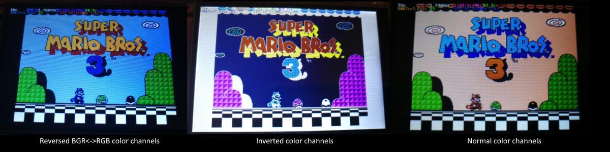
If the color channels are mixed (red is blue, blue is red, green is green) like shown on the left image, pass the CMake option -DDISPLAY_SWAP_BGR=ON to the build.
If the color intensities look wrong (white is black, black is white, color looks like a negative image) like seen in the middle image, pass the CMake option -DDISPLAY_INVERT_COLORS=ON to the build.
If the colors looks off in some other fashion, it is possible that the display is just being driven at a too high SPI bus speed, in which case try making the display run slower by choosing a higher -DSPI_BUS_CLOCK_DIVISOR= option to CMake. Especially on ILI9486 displays it has been observed that the colors on the display can become distorted if the display is run too fast beyond its maximum capability.
fbcp-ili9341 needs a few megabytes of GPU memory to function if DMA transfers are enabled. The gpu_mem boot config option dictates how much of the Pi's memory area is allocated to the GPU. By default this is 64MB, which has been observed to not leave enough memory for fbcp-ili9341 if HDMI is run at 1080p. If this error happens, try increasing GPU memory to eg 128MB by adding a line gpu_mem=128 in /boot/config.txt .
As the number of supported displays, Raspberry Pi device models, Raspbian/Retropie/Lakka OS versions, accompanied C++ compiler versions and fbcp-ili9341 build options have grown in number, there is a combinatorial explosion of all possible build modes that one can put the codebase through, so it is not easy to keep every possible combo tested all the time. Something may have regressed or gotten outdated. Stay calm, and report a bug.
You can also try looking through the commit history to find changes related to your configuration combo, to see if there's a mention of a known good commit in time that should work for your case. If you get an odd compiler error on cmake or make lines, those will usually be very easy to fix, as they are most of the time a result of some configurational oversight.
First, make sure the display is a 4-wire SPI and not a 3-wire one. A display is 4-wire SPI if it has a Data/Control (DC) GPIO line that needs connecting. Sometimes the D/C pin is labeled RS (Register Select). Support for 3-wire SPI displays does exist, but it is experimental and not nearly as well tested as 4-wire displays.
Second is the consideration about display speed. Below is a performance chart of the different displays I have tested. Note that these are sample sizes of one, I don't know how much sample variance there exists. Also I don't know if it is likely that there exists big differences between displays with same controller from different manufacturers. At least the different ILI9341 displays that I have are all quite consistent on performance, whether they are from Adafruit or WaveShare or from BuyDisplay.com.
| Proveedor | Tamaño | Resolución | Controlador | Rated SPI Bus Speed | Obtained Bus Speed | Frame Rate |
|---|---|---|---|---|---|---|
| Adafruit PiTFT | 2.8" | 240x320 | ILI9341 | 10MHz | 294MHz/4=73.50MHz | 59.81 fps |
| Adafruit PiTFT | 2.2" | 240x320 | ILI9340 | 15.15MHz | 338MHz/4=84.50MHz | 68.76 fps |
| Adafruit PiTFT | 3.5" | 320x480 | HX8357D | 15.15MHz | 314MHz/6=52.33MHz | 21.29 fps |
| Adafruit OLED | 1.27" | 128x96 | SSD1351 | 20MHz | 360MHz/20=18.00MHz | 91.55 fps |
| Waveshare RPi LCD (B) IPS | 3.5" | 320x480 | ILI9486 | 15.15MHz | 255MHz/8=31.88MHz | 12.97 fps |
| maithoga TFT LCD | 3.5" | 320x480 | ILI9486L | 15.15MHz | 400MHz/8=50.00MHz | 13.56 fps* |
| BuyDisplay.com SPI TFT copy #1 | 3.2" | 240x320 | ILI9341 | 10MHz | 310MHz/4=77.50MHz | 63.07 fps |
| BuyDisplay.com SPI TFT copy #2 | 3.2" | 240x320 | ILI9341 | 10MHz | 300MHz/4=75.00MHz | 61.03 fps |
| Arduino A000096 LCD | 1.77" | 128x160 | ST7735R | 15.15MHz | 355MHz/6=59.16MHz | 180.56 fps |
| Tontec MZ61581-PI-EXT 2016.1.28 | 3.5" | 320x480 | MZ61581 | 128MHz | 280MHz/2=140.00MHz | 56.97 fps |
| Adafruit 240x240 Wide Angle TFT | 1.54" | 240x240 | ST7789 | ? | 340MHz/4=85.00MHz | 92.23 fps |
| WaveShare 240x240 Display HAT | 1.3" | 240x240 | ST7789VW | 62.5MHz | 338MHz/4=84.50MHz | 91.69 fps |
| WaveShare 128x128 Display HAT | 1.44" | 128x128 | ST7735S | 15.15MHz | (untested) | (untested) |
| KeDei v6.3 | 3.5" | 320x480 | MPI3501 | ? | 400MHz/12=33.333MHz | 4.8fps ** |
In this list, Rated SPI Bus Speed is the maximum clock speed that the display controller is rated to run at. The Obtained Bus Speed column lists the fastest SPI bus speed that was achieved in practice, and the core_freq BCM Core speed and SPI Clock Divider CDIV setting that was used to achieve that rate. Note how most display controllers can generally be driven much faster than what they are officially rated at in their spec sheets.
The Frame Rate column shows the worst case frame rate when full screen updates are being performed. This occurs for example when watching fullscreen video (that is not a flat colored cartoon). Because fbcp-ili9341 only sends over the pixels that have changed, displays such as HX8357D and ILI9486 can still be used to play many games at 60fps. Retro games work especially well.
All the ILI9341 displays work nice and super fast at ~70-80MHz. My WaveShare 3.5" 320x480 ILI9486 display runs really slow compared to its pixel resolution, ~32MHz only. See fbcp-ili9341 ported to ILI9486 WaveShare 3.5" (B) SpotPear 320x480 SPI display for a video of this display in action. Adafruit's 320x480 3.5" HX8357D PiTFTs is ~64% faster in comparison.
The ILI9486L controller based maithoga display runs a bit faster than ILI9486 WaveShare, 50MHz versus 31.88MHz, ie +56.8% bandwidth increase. However fps-wise maithoga reaches only 13.56 vs WaveShare 12.97 fps, because the bandwidth advantage is fully lost in pixel format differences: ILI9486L requires transmitting 24 bits per each pixel (R6G6B6 mode), whereas ILI9486 supports 16 bits per pixel R5G6B5 mode. This is reflected in the above chart refresh rate for the maithoga display (marked with a star).
If manufacturing variances turn out not to be high between copies, and you'd like to have a bigger 320x480 display instead of a 240x320 one, then it is recommended to avoid ILI9486, they indeed are slow.
The KeDei v6.3 display with MPI3501 controller takes the crown of being horrible, in all aspects imaginable. It is able to run at 33.33 MHz, but due to technical design limitations of the display (see #40), effective bus speed is halved, and only about 72% utilization of the remaining bus rate is achieved. DMA cannot be used, so CPU usage will be off the charts. Even though fbcp-ili9341 supports this display, level of support is expected to be poor, because the hardware design is a closed secret without open documentation publicly available from the manufacturer. Stay clear of KeDei or MPI3501 displays.
The Tontec MZ61581 controller based 320x480 3.5" display on the other hand can be driven insanely fast at up to 140MHz! These seem to be quite hard to come by though and they are expensive. Tontec seems to have gone out of business and for example the domain itontec.com from which the supplied instructions sheet asks to download original drivers from is no longer registered. I was able to find one from eBay for testing.
Search around, or ask the manufacturer of the display what the maximum SPI bus speed is for the device. This is the most important aspect to getting good frame rates, but unfortunately most web links never state the SPI speed rating, or they state it ridiculously low like in the spec sheets. Try and buy to see, or ask in some community forums from people who already have a particular display to find out what SPI bus speed it can achieve.
One might think that since Pi Zero is slower than a Pi 3, the SPI bus speed might not matter as much when running on a Pi Zero, but the effect is rather the opposite. To get good framerates on a Pi Zero, it should be paired with a display with as high SPI bus speed capability as possible. This is because the higher the SPI bus speed is, the more autonomously a DMA controller can drive it without CPU intervention. For the same reason, the interlacing technique does not (currently at least) perform well on a Pi Zero, so it is disabled there by default. ILI9341s run well on Pi Zero, ILI9486 on the other hand is quite difficult to combine with a Pi Zero.
Ultimately, it should be noted that parallel displays (DPI) are the proper method for getting fast framerates easily. SPI displays should only be preferred if display form factor is important and a desired product might only exist as SPI and not as DPI, or the number of GPIO pins that are available on the Pi is scarce that sacrificing dozens of pins to RGB data is not factible.
Hardware-wise, there are six different ways to connect displays to the Pi. Here are the pros and cons of each:
Displays are generally manufactured to utilize one specific interfacing method, with the exception that some displays have a both I²C and SPI modes that can be configured via soldering.
Fbcp-ili9341 driver is about interfacing with SPI displays. If your display utilizes some other connection mechanism, fbcp-ili9341 will not apply.
Software-wise, there are two possible alternatives to fbcp-ili9341:
The following links proved helpful when writing this:
If you would like to help push Raspberry Pi SPI display support further, there are always more things to do in the project. Here is a list of ideas and TODOs for recognized work items to contribute, roughly rated in order of increasing difficulty.
top / htop , or with a power meter off the wall and report the results.SPI_3WIRE_PROTOCOL + ALL_TASKS_SHOULD_DMA to work together, or 3) fix up SPI_3WIRE_PROTOCOL + OFFLOAD_PIXEL_COPY_TO_DMA_CPP to work together.ALL_TASKS_SHOULD_DMA mode to be always superior in performance and CPU usage so that the non- ALL_TASKS_SHOULD_DMA path can be dropped from the codebase. (probably requires the above chaining to function efficiently)This driver is licensed under the MIT License. See LICENSE.txt. In nonlegal terms, it's yours for both free and commercial projects, DIY packages, kickstarters, Etsys and Ebays, and you don't owe back a dime. Feel free to apply and derive as you wish.
If you found fbcp-ili9341 useful, it makes me happy to hear back about the projects it found a home in. If you did a build or a project where fbcp-ili9341 worked out, it'd be great to see a video or some photos or read about your experiences.
I hope you build something you enjoy!
Best way to discuss the driver is to open a GitHub issue. You may also be able to find me over at sudomod.com Discord channel.


