fbcp ili9341
1.0.0
L'ère de FBCP-ILI9341 a pris fin. FBCP-ILI9341 a été construit au-dessus de l'API VideoCore Dispmanx de Raspberry Pi.
Cependant, cette API a été obsolète par la Raspberry Pi Foundation depuis un certain temps maintenant, et enfin obsolète (= indisponible) sur Raspberry Pi 5 et en avant.
Les distros de Raspberry Pi ultérieurs n'ont plus de dispmanx actifs par défaut, même pour PI0-PI4, mais à la place, Raspberry Pi s'est déplacé vers la nouvelle pile de compositeur de pilote KMS, qui a une abstraction différente pour intégrer les pilotes d'affichage SPI. D'autres personnes développent des pilotes d'affichage SPI pour le PI qui sont compatibles avec la pile KMS. Rendez-vous sur ce fil de forum Raspberry Pi pour en savoir plus.
Ce référentiel est bon d'être considéré comme archivé / périmé, bien que je ne le marque pas archivé en utilisant la fonction GitHub, car cette fonctionnalité rendrait apparemment le tracker de problème en lecture seule. N'hésitez pas à continuer de discuter des problèmes sur le tracker.
Ce référentiel implémente un pilote pour certains écrans LCD basés sur SPI pour Raspberry Pi A, B, 2, 3, 4 et Zero.

Le travail a été motivé par la curiosité après avoir vu cette série de vidéos sur la chaîne YouTube rétromancave:
Dans ces vidéos, le bus SPI (GPIO) est référé pour être le goulot d'étranglement. Les affichages basés sur SPI mettent à jour sur un bus de données série, transmettant un bit par cycle d'horloge dans le bus. Un écran 320x240x16bpp nécessite donc une fréquence d'horloge de bus SPI de 73,728 MHz pour obtenir une fréquence de rafraîchissement complète de 60fps. Peu de contrôleurs LCD SPI peuvent communiquer aussi rapidement dans la pratique, mais sont limités à une vitesse d'horloge de bus SPI de 16 à 50 MHz, plafonnant considérablement le taux de mise à jour maximal. Pouvons-nous faire quelque chose à ce sujet?
Le projet FBCP-ILI9341 a commencé comme un pilote d'affichage pour l'écran ADAFruit 2.8 "320x240 TFT avec un écran tactile pour Raspberry Pi Affichage qui utilise le contrôleur ILI9341. qui est affiché.
Étant donné que le bus SPI peut être ainsi limité sur la bande passante, comment se fait-il que FBCP-ILI9341 semble être en mesure de mettre à jour jusqu'à 60 images par seconde? La façon dont cela est réalisée est par ce qui pourrait être appelé les mises à jour de flux d'affichage adaptatif . Au lieu de télécharger chaque pixel à chaque cycle de rafraîchissement de l'affichage, seuls les pixels réellement modifiés à l'écran sont soumis à l'écran. Ceci est faisable car le contrôleur ILI9341, comme de nombreux autres contrôleurs populaires, ont des fonctions d'interface de communication qui permettent de spécifier des mises à jour d'écran partielles, jusqu'à des sous-anciens ou même des niveaux de pixels individuels. Cela permet de battre la limite de bande passante: par exemple dans Quake, même s'il s'agit d'un jeu de rythme rapide, en moyenne seulement environ 46% de tous les pixels à l'écran changent chaque cadre rendu. Certaines pièces, telles que l'interface utilisateur, restent pratiquement constantes sur plusieurs images.
D'autres optimisations sont également utilisées pour exprimer encore plus de performances:
#define NO_INTERLACING dans le fichier config.h )Le résultat est que le bus SPI peut être maintenu près de 100% de saturation, ~ 94-97% habituel, pour maximiser le taux d'utilisation du bus, tout en transmettant uniquement le nombre minimum d'octets nécessaires pour décrire chaque nouvelle image.
Le conducteur a été vérifié pour fonctionner (au moins un point dans le passé) sur les systèmes suivants:
Bien que toutes les planches ne soient pas testées activement, donc YMMV, en particulier sur les planches plus anciennes. (Bogue correcte bienvenue, utilisez https://elinux.org/rpi_hardwarehistory pour identifier la carte sur laquelle vous utilisez)
Les écrans LCD suivants ont été testés:
Vérifiez les sections suivantes pour configurer le pilote.
Ce pilote n'utilise pas le pilote notro / fbtft framebuffer, il faut donc désactiver s'il est actif. Autrement dit, si votre fichier /boot/config.txt a des lignes qui ressemblent à quelque chose comme dtoverlay=pitft28r, ... , dtoverlay=waveshare32b, ... ou dtoverlay=flexfb, ... , celles-ci doivent être supprimées.
Ce programme n'utilise pas le pilote SPI par défaut, de sorte qu'une ligne telle que dtparam=spi=on in /boot/config.txt doit également être supprimée afin qu'elle ne provoque pas de conflits.
De même, si vous avez des dtoverlays liés au contrôleur tactile actifs, tels que dtoverlay=ads7846,... ou tout ce qui a une directive penirq= , ceux-ci doivent également être supprimés pour éviter les conflits. Il serait possible d'ajouter un support tactile à FBCP-ILI9341 si quelqu'un veut le poignarder.
Courez dans la console de votre Raspberry Pi:
sudo apt-get install cmake
cd ~
git clone https://github.com/juj/fbcp-ili9341.git
cd fbcp-ili9341
mkdir build
cd build
cmake [options] ..
make -j
sudo ./fbcp-ili9341
Remarque en particulier les deux points .. sur la ligne CMake, qui désignent "Up One Directory" dans ce cas (au lieu de se référer à "plus d'éléments Go ici").
Voir la section suivante pour voir quoi saisir sous [Options] .
Si vous avez exécuté le pilote fbcp existant, assurez-vous de supprimer cela par exemple via un sudo pkill fbcp (tout en fonctionnant dans l'invite SSH ou connecté à un écran HDMI), ces deux ne peuvent pas fonctionner en même temps. Si /etc/rc.local ou /etc/init.d contient une entrée pour démarrer fbcp au démarrage, cette directive doit être supprimée.
Il existe généralement deux façons de configurer les options de construction, sur la ligne de commande CMake, et dans le fichier config.h.
Sur la ligne de commande CMake, les options suivantes peuvent être configurées:
Lorsque vous utilisez l'un des écrans qui s'empilent au-dessus du PI qui sont déjà reconnus par FBCP-ILI9341, vous n'avez pas besoin de spécifier les affectations de broches GPIO, mais le code FBCP-ILI9341 en a déjà. Passez l'une des directives CMake suivantes pour les chapeaux:
-DADAFRUIT_ILI9341_PITFT=ON : Si vous utilisez sur l'Adafruit 2.8 "320x240 TFT avec un écran tactile pour Raspberry Pi (ou Adafruit Pitft 2.2" Hat Mini Kit - 320x240 2,2 "TFT - No Touch Affich drapeau.-DADAFRUIT_HX8357D_PITFT=ON : Si vous avez le pitft Adafruit - assemblé 480x320 3,5 "tft + écran tactile pour l'affichage PI Raspberry, ajoutez cette ligne.-DFREEPLAYTECH_WAVESHARE32B=ON : Si vous utilisez le périphérique FreePlay CM3 ou Zero, passez cet drapeau. (Ce n'est pas un chapeau, mais toujours une affectation d'épingle préconfigurée)-DWAVESHARE35B_ILI9486=ON : Si spécifié, cible un affichage Waveshare 3,5 "480x320 Ili9486.-DTONTEC_MZ61581=ON : Si vous utilisez l'affichage de l'écran LCD Tontec 3.5 "320x480, passez ceci.-DPIRATE_AUDIO_ST7789_HAT=ON : Si spécifié, cible un pirate Audio 240x240, 1,3 pouce d'écran IPS pour Raspberry Pi avec le contrôleur d'affichage ST7789-DWAVESHARE_ST7789VW_HAT=ON : Si spécifié, cible un chapeau d'affichage LCD IPS 240x240, 1,3 pouce pour Raspberry Pi avec le contrôleur d'affichage ST7789VW.-DWAVESHARE_ST7735S_HAT=ON : si spécifié, cible un chapeau d'affichage LCD 128x128, 1,44 pouce pour Raspberry Pi avec le contrôleur d'affichage ST7735S.-DKEDEI_V63_MPI3501=ON : Si spécifié, cible un KEDEI 3,5 pouces SPI TFTLCD 480 * 320 16bit / 18bit version 6.3 2018/4/9 Affichage avec contrôleur d'affichage MPI3501. Si vous avez connecté des fils directement sur le PI au lieu d'utiliser un chapeau de la liste ci-dessus, vous devrez utiliser les directives de configuration ci-dessous. En plus de spécifier l'affichage, vous devrez également indiquer à FBCP-ILI9341 à quels broches GPIO vous avez câblé les connexions. Pour configurer le contrôleur d'affichage, passez l'un des:
-DILI9341=ON : Si vous utilisez un autre affichage générique ILI9341, ou sur l'écran Waveshare32b qui est autonome et non sur le périphérique FreePlaytech CM3 / Zero, passez cet drapeau.-DILI9340=ON : Si vous avez un affichage Ili9340, passez cette directive. Les chipsets ILI9340 et ILI9341 sont très similaires, mais ILI9340 ne prend pas en charge toutes les fonctionnalités sur ILI9341 et ils seront désactivés ou rétrogradés.-DHX8357D=ON : Si vous avez un écran HX8357D, passez cette directive.-DSSD1351=ON : Si vous avez un écran OLED SSD1351, utilisez-le.-DST7735R=ON : Si vous avez un écran ST7735R, utilisez-le.-DST7789=ON : Si vous avez un écran ST7789, utilisez-le.-DST7789VW=ON : Si vous avez un écran ST7789VW, utilisez-le.-DST7735S=ON : Si vous avez un écran ST7735S, utilisez-le.-DILI9486=ON : Si vous avez un affichage Ili9486, passez cette directive.-DILI9486L=ON : Si vous avez un affichage Ili9486l, passez cette directive. Notez que Ili9486 et Ili9486l sont des puces de contrôleur très différentes, mutuellement incompatibles, alors soyez prudent ici, identifiant celui que vous avez. (ou juste essayer les deux, ne devrait pas se casser si vous avez mal identifié)-DILI9488=ON : Si vous avez un affichage Ili9488, passez cette directive.-DMPI3501=ON : Si spécifié, cible un affichage avec contrôleur d'affichage MPI3501.Et en outre, passez ce qui suit pour personnaliser les affectations de broches GPIO que vous avez utilisées:
-DGPIO_TFT_DATA_CONTROL=number : Spécifie / remplace la broche GPIO à utiliser pour la ligne Data / Control (DC) sur la communication SPI à 4 fils. Ce numéro de broche est spécifié dans les numéros de broches BCM. Si vous avez un affichage SPI à 3 fils qui n'a pas de ligne de données / contrôle, définissez cette valeur sur -1 , IE -DGPIO_TFT_DATA_CONTROL=-1 pour dire à FBCP-Ili9341 pour cibler 3 wire ("9 bits") SPI communication.-DGPIO_TFT_RESET_PIN=number : spécifie / remplace la broche gpio à utiliser pour la ligne de réinitialisation d'affichage. Ce numéro de broche est spécifié dans les numéros de broches BCM. S'il est omis, il est supposé que l'affichage n'a pas de broche de réinitialisation et est toujours allumé.-DGPIO_TFT_BACKLIGHT=number : spécifie / remplace la broche gpio à utiliser pour la ligne de rétro-éclairage d'affichage. Ce numéro de broche est spécifié dans les numéros de broches BCM. S'il est omis, il est supposé que l'affichage n'a pas de broche de rétroéclairage contrôlée par GPIO et est toujours allumée. Si vous définissez ceci, consultez également l'option #define BACKLIGHT_CONTROL dans config.h .FBCP-ILI9341 utilise toujours le port SPI0 matériel, donc les broches MISO, MOSI, CLK et CE0 sont toujours les mêmes et ne peuvent pas être modifiées. La broche MISO n'est en fait pas utilisée (au moins au moins), vous pouvez donc simplement sauter la connexion. Si votre écran est un voyou qui ignore la ligne d'activation de la puce, vous pouvez omettre de connecter cela également, ou peut également être en mesure de vous éloigner en connectant cela à la terre si vous avez du mal à simplifier le câblage (selon l'écran).
Pour obtenir de bonnes performances des écrans, vous conduirez les écrans bien au-dessus des spécifications de vitesse nominales (les spécifications nominales donnent environ ~ 10fps selon l'affichage). Pour cette raison, vous devrez configurer explicitement la vitesse cible dans laquelle vous souhaitez piloter l'affichage, car en raison des écarts de fabrication, chaque copie d'affichage atteint une vitesse maximale différente. Il n'y a pas de "vitesse par défaut" que FBCP-ILI9341 utiliserait. Le réglage de la vitesse se fait via l'option
-DSPI_BUS_CLOCK_DIVISOR=even_number : Définit le numéro de diviseur d'horloge qui, avec l'option PI Core_freq = dans /boot/config.txt spécifie la vitesse globale à laquelle le bus de communication SPI d'affichage est piloté. SPI_frequency = core_freq/divisor . SPI_BUS_CLOCK_DIVISOR doit être un nombre pair. Pi 3B par défaut et zéro w core_freq sont 400 MHz, et généralement une valeur -DSPI_BUS_CLOCK_DIVISOR=6 semble être la meilleure qu'un affichage Ili9341 puisse faire. Essayez une valeur plus grande si l'écran affiche une sortie corrompue ou une valeur plus petite pour obtenir une bande passante plus élevée. Voir ili9341.h et waveshare35b.h pour les points de données sur le réglage des performances SPI maximales. La valeur initiale sûre pourrait être quelque chose comme -DSPI_BUS_CLOCK_DIVISOR=30 . Il existe quelques options pour dire explicitement quelle carte PI vous souhaitez cibler. Ceux-ci devraient être automatiquement autonomes pour vous et ne sont généralement pas nécessaires, mais par exemple si vous compiliez croisé pour une autre carte PI à partir d'un autre système, ou si vous souhaitez être explicite, vous pouvez essayer:
-DSINGLE_CORE_BOARD=ON : Passez cette option si vous utilisez un PI qui n'a qu'un seul thread matériel (PI Model A, PI Model B, Compute Module 1, Pi Zero / Zero W). Si ce n'est pas présent, automatiquement.-DARMV6Z=ON : Passez cette option pour optimiser spécifiquement le jeu d'instructions ARMV6Z (PI 1A, 1A +, 1B, 1B +, ZERO, ZERO W). Si ce n'est pas présent, automatiquement.-DARMV7A=ON : Passez cette option pour optimiser spécifiquement le jeu d'instructions ARMV7-A (PI 2B <Rev 1.2). Si ce n'est pas présent, automatiquement.-DARMV8A=ON : Passez cette option pour optimiser spécifiquement le jeu d'instructions ARMV8-A (PI 2B> = rév. 1.2, 3b, 3b +, CM3, CM3 Lite, 4b, CM4, PI400). Si ce n'est pas présent, automatiquement. Les options de construction suivantes sont générales pour tous les écrans et les cartes PI, ils personnalisent davantage la construction:
-DBACKLIGHT_CONTROL=ON : Si set, permet à FBCP-ILI9341 de contrôler le rétro-éclairage d'affichage dans la broche de rétroéclairage donnée. L'affichage s'endormera après une période d'inactivité à l'écran. Sinon, le rétroéclairage n'est pas touché.-DDISPLAY_CROPPED_INSTEAD_OF_SCALING=ON : Si définissez, et le cadre vidéo source est plus grand que la résolution vidéo d'affichage SPI, la vidéo source est présentée sur l'affichage SPI en recueillant des parties de celui-ci dans toutes les directions, au lieu de mettre à l'échelle pour s'adapter.-DDISPLAY_BREAK_ASPECT_RATIO_WHEN_SCALING=ON : Lors de l'échelle de la vidéo source à l'affichage SPI, la mise à l'échelle est effectuée par défaut suivant le rapport d'aspect, ajoutant des boîtes de lettres / pilier au besoin. Si cela est défini, l'étirement est effectué le rapport d'aspect de rupture.-DSTATISTICS=number : Spécifie le niveau des statistiques de superposition à afficher à l'écran. 0: Désactivé, 1: Activé, 2: Activé et afficher également le graphique d'intervalle de fréquence d'images. La valeur par défaut est 1 (activée).-DUSE_DMA_TRANSFERS=OFF : Si spécifié, désactive à l'aide de transferts DMA (à grands frais de l'utilisation du processeur perdu). Passez cette directive si DMA donne quelques problèmes, par exemple comme une étape de dépannage si quelque chose ne semble pas correct.-DDMA_TX_CHANNEL=<num> : spécifie le numéro de canal DMA à utiliser pour les commandes SPI Send. Changez-le si vous trouvez un conflit de canal DMA.-DDMA_RX_CHANNEL=<num> : spécifie le numéro de canal DMA à utiliser pour les commandes de réception SPI. Changez-le si vous trouvez un conflit de canal DMA.-DDISPLAY_SWAP_BGR=ON : Si cette option est passée, les canaux de couleur rouge et bleu sont inversés (RGB <-> BGR). Certains écrans ont une disposition de sous-pixels de panneau de couleur opposée que le contrôleur d'affichage ne tient pas automatiquement, alors définissez ceci si le bleu et le rouge sont mélangés.-DDISPLAY_INVERT_COLORS=ON : Si cette option est passée, l'interprétation de la valeur de couleur pixel est inversée (blanc = 0, noir = 31/63). Par défaut: noir = 0, blanc = 31/63. Passez cette option si l'image d'affichage ressemble à une couleur négative des couleurs réelles.-DDISPLAY_ROTATE_180_DEGREES=ON : Si le jeu, l'affichage est tourné de 180 degrés. Cela n'affecte pas la sortie HDMI, seulement la sortie d'affichage SPI.-DLOW_BATTERY_PIN=<num> : Spécifie une broche GPIO qui peut être interrogée pour obtenir l'état de la batterie. Par défaut, lorsque celle-ci est définie, une icône de batterie faible s'affiche si la broche est tirée bas (voir config.h pour les moyens par lesquels cela peut être modifié). En plus des directives CMake ci-dessus, il existe divers définies dispersées autour de la base de code, principalement dans config.h, qui contrôlent différentes options d'exécution. Modifiez-les directement pour régler davantage le comportement du programme. En particulier, après avoir terminé la configuration, vous voudrez peut-être construire avec -DSTATISTICS=0 option dans la ligne de configuration CMake.
Voici un exemple complet de ce qu'il faut taper et exécuter, si vous avez l'Adafruit 2.8 "320x240 TFT avec un écran tactile pour Raspberry Pi avec contrôleur ILI9341:
 cd ~
sudo apt-get install cmake
git clone https://github.com/juj/fbcp-ili9341.git
cd fbcp-ili9341
mkdir build
cd build
cmake -DSPI_BUS_CLOCK_DIVISOR=6 -DADAFRUIT_ILI9341_PITFT=ON ..
make -j
sudo ./fbcp-ili9341
Si ce qui précède ne fonctionne pas, essayez de spécifier -DSPI_BUS_CLOCK_DIVISOR=8 ou =10 pour faire fonctionner l'affichage un peu plus lent, ou essayez avec -DUSE_DMA_TRANSFERS=OFF pour dépanner si DMA peut être le problème. Si vous utilisez un autre contrôleur d'affichage que ILI9341, en utilisant une valeur beaucoup plus élevée, comme 30 ou 40 peuvent être nécessaires. Lorsque vous modifiez les options CMake, vous pouvez rééditer la ligne de directive CMake sans avoir à refléter ou à recréer le répertoire build . Cependant, vous devrez peut-être supprimer manuellement le fichier cmakecache.txt entre la modification des options pour éviter que les anciens paramètres de se souvenir des anciens.
Si vous souhaitez effectuer une reconstruction complète à partir de zéro, vous pouvez rm -rf build pour supprimer le répertoire de construction et le recréer pour une reconstruction propre à partir de zéro. Il n'y a rien de spécial dans le nom ou l'emplacement de ce répertoire, c'est juste ma convention habituelle. Vous pouvez également faire la construction dans un autre répertoire par rapport au répertoire FBCP-ILI9341 si vous le souhaitez.
Pour configurer le pilote pour lancer au démarrage, modifiez le fichier /etc/rc.local en mode sudo et ajoutez une ligne
sudo /path/to/fbcp-ili9341/build/fbcp-ili9341 & à la fin. Notez les ampères & à la fin de cette ligne nécessaire.
Par exemple, si vous avez utilisé les étapes de ligne de commande répertoriées ci-dessus pour construire, le fichier /etc/rc.local recevrait une ligne
sudo /home/pi/fbcp-ili9341/build/fbcp-ili9341 & Si le nom d'utilisateur de votre installation Raspberry Pi est autre chose que le pi par défaut, modifiez le répertoire en conséquence pour pointer vers le répertoire personnel de l'utilisateur. (Utilisez pwd pour découvrir le répertoire actuel dans le terminal)
systemd Alternativement, au lieu de modifier /etc/rc.local , utilisez le fichier unitaire systemd fourni comme ci-dessous:
sudo install -m 0644 -t /etc fbcp-ili9341.conf
sudo install -m 0644 -t /etc/systemd/system fbcp-ili9341.service
sudo systemctl daemon-reload
sudo systemctl enable fbcp && sudo systemctl start fbcp Si la taille de la sortie HDMI par défaut /dev/fb0 FrameBuffer diffère de la résolution de l'écran, la taille de la vidéo source sera par défaut pour s'adapter à la taille de l'écran SPI. FBCP-ILI9341 gérera la mise en place de ce rediffusion si nécessaire, et il sera fait par le GPU, donc les performances ne doivent pas être trop impactées. Cependant, si les résolutions ne correspondent pas, le petit texte semblera probablement illisible. Le redimensionnement sera effectué de manière de préserver le rapport d'aspect, donc si les rapports d'aspect ne correspondent pas, les bordures noires horizontales ou verticales apparaîtront sur l'affichage. Si vous n'utilisez pas du tout la sortie HDMI, il est probablement préférable de configurer la sortie HDMI pour correspondre à la taille de l'affichage SPI afin que le rediffusion ne soit pas nécessaire. Cela peut être fait en définissant les lignes suivantes dans /boot/config.txt :
 hdmi_group=2
hdmi_mode=87
hdmi_cvt=320 240 60 1 0 0 0
hdmi_force_hotplug=1
Si votre écran SPI a une résolution différente de 320x240, modifiez la partie 320 240 en par exemple 480 320 .
Ces lignes suggèrent les applications natives sur le mode d'affichage par défaut et les permettent de rendre à la résolution native de l'écran TFT. Cela peut cependant empêcher l'utilisation du connecteur HDMI, si l'affichage connecté HDMI ne prend pas en charge une telle résolution aussi petite. En tant que compromis, si les écrans HDMI et SPI souhaitent être utilisés en même temps, une autre résolution compatible telle que 640x480 peut être utilisée. Voir Raspberry PI HDMI Documentation pour les options disponibles pour ce faire.
La vitesse de rafraîchissement de l'écran est dictée par la vitesse d'horloge du bus SPI auquel l'affichage est connecté. En raison de la façon dont fonctionne la puce BCM2835 sur Raspberry Pi, il n'existe pas une option simple speed=xxx Mhz qui pourrait être réglée pour définir la vitesse du bus. Au lieu de cela, la vitesse du bus SPI est dérivée de deux paramètres distincts: la fréquence centrale du SOC BCM2835 en général ( core_freq dans /boot/config.txt ) et le paramètre SPI périphérique CDIV (diviseur d'horloge). Ensemble, la vitesse de bus SPI résultante est ensuite calculée avec la formule SPI_speed=core_freq/CDIV .
Pour optimiser l'affichage pour fonctionner le plus rapidement possible,
Ajustez la valeur CDIV en passant la directive -DSPI_BUS_CLOCK_DIVISOR=number dans la ligne de commande cmake. Les valeurs possibles sont même des nombres 2 , 4 , 6 , 8 , ... Notez que comme CDIV apparaît dans le dénominateur dans la formule pour SPI_speed , des valeurs plus petites entraînent des vitesses de bus plus élevées, tandis que des valeurs plus élevées rendent l'affichage plus lentement. Initialement, lorsque vous ne savez pas à quelle vitesse votre affichage peut fonctionner, essayez de commencer par un paramètre élevé sûr, tel que -DSPI_BUS_CLOCK_DIVISOR=30 , et vous frayez un chemin vers des nombres plus petits pour trouver la vitesse maximale à laquelle l'écran peut faire face. Voir le tableau à la fin de la lecture pour des vitesses de bus maximales observées spécifiques pour différents écrans.
Assurer la vitesse de la turbo. Ceci est essentiel pour les bonnes fréquences d'images. Sur le modèle B Raspberry PI 3, le noyau BCM2835 s'exécute par défaut à 400 MHz (résultant en une vitesse SPI 400/CDIV MHz) s'il y a suffisamment de puissance fournie au PI, et si la température du CPU ne dépasse pas les limites thermiques. Si le processeur est inactif ou si la tension est faible, le noyau BCM2835 reviendra plutôt à l'état non turbo 250 MHz, ce qui entraîne une vitesse SPI 250/CDIV MHz. Cet effet de la vitesse turbo sur les performances est significatif, car 400 MHz vs non turbo 250 MHz s'élève à + 60% de la bande passante supplémentaire. Obtenir 60 images par seconde en tremblement de terre, sonic ou tyrien nécessite souvent cette fréquence turbo, mais par exemple, les jeux émulés par C64 peuvent souvent atteindre 60 images par seconde même avec le stock de 250 MHz. Si, pour une raison quelconque, la protection sous tension est en train de faire un coup de pied, même lorsque suffisamment de puissance doit être alimentée, vous pouvez forcer le turbo en activité lorsque la basse tension est présente en définissant la valeur avoid_warnings=2 dans le fichier /boot/config.txt .
Peut-être un peu contre-intuitivement, sous-classe le noyau. Le réglage d'une fréquence centrale plus petite que le turbo par défaut de 400 MHz peut permettre d'utiliser un diviseur d'horloge plus petit pour obtenir une vitesse de bus SPI résultant. Par exemple, si avec core_freq=400 SPI CDIV=8 fonctionne avec par défaut (résultant en une vitesse de bus SPI 400MHz/8=50MHz ), mais CDIV=6 ne le fait pas ( 400MHz/6=66.67MHz était trop), vous pouvez essayer de réduire core_freq=360 et définir CDIV=6 pour obtenir une vitesse de bus SPI efficace de 360MHz/6=60MHz , un terrain d'entente entre les deux qui pourraient peut-être fonctionner. Équilibrer les options core_freq= et CDIV permet de trouver la vitesse maximale de bus SPI jusqu'à les derniers kHz que le contrôleur d'affichage peut tolérer. On peut également essayer la direction opposée et l'overclocking, mais cela a alors bien sûr tous les problèmes qui se présentent lors de l'overclocking. Le sous-blocage a l'inconvénient qu'il rend le PI plus lent dans l'ensemble, donc c'est certainement un compromis.
D'un autre côté, il est souhaitable de contrôler la quantité de temps CPU FBCP-ILI9341 est autorisé à utiliser. Les paramètres de construction par défaut sont réglés pour maximiser le taux de rafraîchissement de l'affichage au détriment de la consommation d'énergie sur PI 3B. Sur Pi Zero, l'inverse est terminé, c'est-à-dire par défaut que le pilote optimise pour l'enregistrement de la batterie au lieu de la vitesse de mise à jour de l'affichage maximale. Les options suivantes peuvent être contrôlées pour équilibrer entre ces deux:
L'option principale pour contrôler l'utilisation du processeur par rapport à l'aspect performances est l'option #define ALL_TASKS_SHOULD_DMA dans config.h . L'activation de cette option réduira considérablement l'utilisation du processeur. Si cette option est désactivée, l'utilisation des bus SPI est maximisée, mais l'utilisation du processeur peut atteindre 80% à 120%. Lorsque cette option est activée, l'utilisation du processeur est généralement jusqu'à environ 15% à 30%. L'utilisation maximale du processeur se produit lorsque vous regardez une vidéo ou en jouant à un jeu en mouvement rapide. Si rien ne change à l'écran, la consommation du processeur du conducteur devrait baisser très près de 0 à 5%. Par défaut, #define ALL_TASKS_SHOULD_DMA est activé pour pi zéro, mais désactivé pour pi 3b.
L'option CMake -DUSE_DMA_TRANSFERS=ON doit toujours être activée pour une bonne utilisation du processeur faible. Si les transferts DMA sont désactivés, le pilote s'exécutera en mode SPI interrogé, qui utilise généralement un seul noyau dédié complet de temps de CPU. Si les transferts DMA causent des problèmes, essayez d'ajuster les canaux DMA Send et Recevoir pour la communication SPI avec -DDMA_TX_CHANNEL=<num> et -DDMA_RX_CHANNEL=<num> Cmake options.
La superposition des statistiques imprime des informations assez détaillées sur l'état d'exécution. La désactivation de la superposition avec -DSTATISTICS=0 option pour CMake améliore les performances et réduit l'utilisation du processeur. Si vous souhaitez continuer d'imprimer des statistiques, vous pouvez essayer d'augmenter l'intervalle avec l'option #define STATISTICS_REFRESH_INTERVAL <timeInMicroseconds> dans config.h.
L'activation #define USE_GPU_VSYNC réduit la consommation de processeur, mais en raison de RaspberryPI / Userland # 440 peut provoquer un bégaiement. La désactivation de #defined USE_GPU_VSYNC produit moins de bégaiement, mais en raison de RaspberryPI / Userland # 440, augmente la consommation d'énergie du processeur.
L'option #define SELF_SYNCHRONIZE_TO_GPU_VSYNC_PRODUCED_NEW_FRAMES peut être utilisée en conjonction avec #define USE_GPU_VSYNC pour essayer de trouver un terrain entre le framboise / userland # 440 problèmes - modéré à peu de basculement tout en n'essayant pas de trop consommer CPU. Essayez d'expérimenter l'activation ou la désactivation de ce paramètre.
Il existe un certain nombre d'options #define SAVE_BATTERY_BY_x dans config.h, qui sont toutes par défaut. Ceux-ci devraient être toujours sûrs à utiliser sans compromis. Si vous rencontrez des problèmes liés à la latence ou aux performances, vous pouvez essayer de les basculer pour dépanner.
L'option #define DISPLAY_FLIP_ORIENTATION_IN_SOFTWARE provoque un peu d'utilisation supplémentaire du processeur, donc la désactivation allège un peu la charge du processeur.
Si votre bus d'affichage SPI est en mesure de fonctionner très rapidement par rapport à la taille de l'affichage et à la quantité de contenu changeant à l'écran, vous pouvez essayer d'activer l'option #define UPDATE_FRAMES_IN_SINGLE_RECTANGULAR_DIFF dans config.h pour réduire l'utilisation du CPU au détriment de l'augmentation de l'augmentation Le nombre d'octets envoyés sur le bus. Cela a été observé comme ayant un grand effet sur Pi Zero, il vaut donc la peine d'être vérifié surtout là-bas.
Si le bus d'affichage SPI est capable de fonctionner très très rapidement (ou si vous ne vous souciez pas de la fréquence d'images, mais juste de #define UPDATE_FRAMES_WITHOUT_DIFFING faible utilisation config.h processe option complètement. Cela reviendra à des mises à jour complètes naïves pour une utilisation globale globale absolument minimale.
L'option #define RUN_WITH_REALTIME_THREAD_PRIORITY peut être activée pour que le pilote s'exécute à la priorité du processus en temps réel. Cela peut cependant verrouiller le système, mais toujours mis à disposition pour une expérimentation avancée.
Dans display.h il existe une option #define TARGET_FRAME_RATE <number> . Le régler sur une valeur plus petite, comme 30, échangera le taux de rafraîchissement pour réduire la consommation de processeur.
Un aspect agréable de FBCP-ILI9341 est qu'il introduit très peu de frais de latence: sur un affichage d'ILI9341 rafraîchissant 119Hz, FBCP-ILI9341 obtient des pixels comme réponse de l'entrée GPIO à l'écran dans bien moins de 16,66 msecs. Je n'ai qu'une caméra d'enregistrement de 120 images par seconde, donc je ne peux pas facilement mesurer les retards plus courts que cela, mais une estimation statistique approximative des séquences vidéo au ralenti suggère que ce retard pourrait être aussi faible que 2-3 msecs, dominé par le panneau de rafale de ~ 8,4 mscs de l'ILI9341.
Cela ne signifie pas que la contribution globale pour afficher la latence dans les jeux serait si immédiate. Test brièvement un jeu imité NES dans RetroPie suggère une latence totale d'environ 60 à 80 ms. Cette latence est causée par les frais généraux de l'émulateur de jeu NES et la latence supplémentaire ajoutée par le rendu Linux, Dispmanx et GPU, et l'instantané GPU FrameBuffer. (Si vous avez exécuté FBCP-ILI9341 en tant que bibliothèque statique en contournant DispManx et la pile GPU, reliant directement votre gpio d'entrée et de logique d'application dans FBCP-ILI9341, vous pourriez atteindre ces quelques MSEC de latence globale, comme dans le montant dans le montant dans le montant dans la ci-dessus la vidéo d'entrée GPIO)
Fait intéressant, FBCP-ILI9341 est environ ~ 33 mscs plus rapide qu'un écran Kedei HDMI de 3,5 "bon marché. Le latence aérienne.
Malheureusement, une limitation des écrans connectés SPI est que le signal de ligne VSYNC n'est pas disponible sur les contrôleurs d'affichage lorsqu'ils fonctionnent en mode SPI, il n'est donc pas possible de faire des mises à jour verrouillées VSYNC même si la bande passante de bus SPI sur l'écran était suffisamment rapide était assez rapide . Par exemple, les 4 affichages ILI9341 que j'ai peuvent tous être exécutés plus rapidement que 75 MHz, donc SPI Bus Bandwidth, tous pourraient mettre à jour un cadre complet en moins d'un intervalle VSYNC, mais il n'est pas possible de synchroniser les mises à jour des mises vsync since the display controllers do not report it. (If you do know of a display that does actually expose a vsync clock signal even in SPI mode, you can try implementing support to locking on to it)
You can however choose between two distinct types of tearing artifacts: straight line tearing and diagonal tearing . Whichever looks better is a bit subjective, which is why both options exist. I prefer the straight line tearing artifact, it seems to be less intrusive than the diagonal tearing one. To toggle this, edit the option #define DISPLAY_FLIP_ORIENTATION_IN_SOFTWARE in config.h . When this option is enabled, fbcp-ili9341 produces straight line tearing, and consumes a tiny few % more CPU power. By default Pi 3B builds with straight line tearing, and Pi Zero with the faster diagonal tearing. Check out the video Latency and tearing test #2: GPIO input to display latency in fbcp-ili9341 and tearing modes to see in slow motion videos how these two tearing modes look like.
Another option that is known to affect how the tearing artifact looks like is the internal panel refresh rate. For ILI9341 displays this refresh rate can be adjusted in ili9341.h , and this can be set to range between ILI9341_FRAMERATE_61_HZ and ILI9341_FRAMERATE_119_HZ (default). Slower refresh rates produce less tearing, but have higher input-to-display latency, whereas higher refresh rates will result in the opposite. Again visually the resulting effect is a bit subjective.
To get tearing free updates, you should use a DPI display, or a good quality HDMI display. Beware that cheap small 3.5" HDMI displays such as KeDei do also tear - that is, even if they are controlled via HDMI, they don't actually seem to implement VSYNC timed internal operation.
Having no vsync is not all bad though, since with the lack of vsync, SPI displays have the opportunity to obtain smoother animation on content that is not updating at 60Hz. It is possible that content on the SPI display will stutter even less than what DPI or HDMI displays on the Pi can currently provide (although I have not been able to test this in detail, except for the KeDei case above).
The main option that affects smoothness of display updates is the #define USE_GPU_VSYNC line in config.h . If this is enabled, then the internal Pi GPU HDMI vsync clock is used to drive frames onto the display. The Pi GPU clock runs at a fixed rate that is independent of the content. This rate can be discovered by running tvservice -s on the Pi console, and is usually 59Hz or 60Hz. If your application renders at this rate, animation will look smooth, but if not, there will be stuttering. For example playing a PAL NES game that updates at 50Hz with HDMI clock set at 60Hz will cause bad microstuttering in video output if #define USE_GPU_VSYNC is enabled.
If USE_GPU_VSYNC is disabled, then a busy spinning GPU frame snapshotting thread is used to drive the updates. This will produce smoother animation in content that does not maintain a fixed 60Hz rate. Especially in OpenTyrian, a game that renders at a fixed 36fps and has slowly scrolling scenery, the stuttering caused by USE_GPU_VSYNC is particularly visible. Running on Pi 3B without USE_GPU_VSYNC enabled produces visually smoother looking scrolling on an Adafruit 2.8" ILI9341 PiTFT set to update at 119Hz, compared to enabling USE_GPU_VSYNC on the same setup. Without USE_GPU_VSYNC , the dedicated frame polling loop thread "finds" the 36Hz update rate of the game, and then pushes pixels to the display at this exact rate. This works nicely since SPI displays disregard vsync - the result is that frames are pushed out to the SPI display immediately as they become available, instead of pulling them at a fixed 60Hz rate like HDMI does.
A drawback is that this kind of polling consumes more CPU time than the vsync option. The extra overhead is around +34% of CPU usage compared to the vsync method. It also requires using a background thread, and because of this, it is not feasible to be used on a single core Pi Zero. If this polling was unnecessary, this mode would also work on a Pi Zero, and without the added +34% CPU overhead on Pi 3B. See the Known Issues section below for more details.

There are two other main options that affect frame delivery timings, #define SELF_SYNCHRONIZE_TO_GPU_VSYNC_PRODUCED_NEW_FRAMES and #define SAVE_BATTERY_BY_PREDICTING_FRAME_ARRIVAL_TIMES . Check out the video fbcp-ili9341 frame delivery smoothness test on Pi 3B and Adafruit ILI9341 at 119Hz for a detailed side by side comparison of these different modes. The conclusions drawn from the four tested scenarios in the video are:
1. vc_dispmanx_vsync_callback() (top left) , set #define USE_GPU_VSYNC and unset #define SELF_SYNCHRONIZE_TO_GPU_VSYNC_PRODUCED_NEW_FRAMES :
This mode uses the DispmanX HDMI vsync signal callback to drive frames to the display.
Avantages:
Inconvénients:
2. vc_dispmanx_vsync_callback() + self synchronization (top right) , set #define USE_GPU_VSYNC and #define SELF_SYNCHRONIZE_TO_GPU_VSYNC_PRODUCED_NEW_FRAMES :
This mode uses the GPU vsync signal, but also aims to find and synchronize to the edge trigger when content is producing frames. This is the default build mode on Pi Zero.
Avantages:
Inconvénients:
3. gpu polling thread + sleep heuristic (bottom left) , unset #define USE_GPU_VSYNC and set #define SAVE_BATTERY_BY_PREDICTING_FRAME_ARRIVAL_TIMES :
This mode runs a dedicated background thread that drives frames from the GPU to the SPI display. This is the default build mode on Pi 3B.
Avantages:
Inconvénients:
4. gpu polling thread without sleeping (bottom right) , unset #define USE_GPU_VSYNC and unset #define SAVE_BATTERY_BY_PREDICTING_FRAME_ARRIVAL_TIMES :
This mode runs the dedicated GPU thread as fast as possible, without attempting to sleep CPU.
Avantages:
Inconvénients:
Be aware of the following limitations:
vc_dispmanx_snapshot() API, and the obtained pixels are then routed on to the SPI-based display. This kind of polling is performed, since there does not exist an event-based mechanism to get new frames from the GPU as they are produced. The result is inefficient and can easily cause stuttering, since different applications produce frames at different paces. Ideally the code would ask the VideoCore API to receive finished frames in callback notifications immediately after they are rendered , but this kind of functionality does not exist in the current GPU driver stack. In the absence of such event delivery mechanism, the code has to resort to polling snapshots of the display framebuffer using carefully timed heuristics to balance between keeping latency and stuttering low, while not causing excessive power consumption. These heuristics keep continuously guessing the update rate of the animation on screen, and they have been tuned to ensure that CPU usage goes down to 0% when there is no detected activity on screen, but it is certainly not perfect. This GPU limitation is discussed at raspberrypi/userland#440. If you'd like to see fbcp-ili9341 operation reduce latency, stuttering and power consumption, please throw a (kind!) comment or a thumbs up emoji in that bug thread to share that you care about this, and perhaps Raspberry Pi engineers might pick the improvement up on the development roadmap. If this issue is resolved, all of the #define USE_GPU_VSYNC , #define SAVE_BATTERY_BY_PREDICTING_FRAME_ARRIVAL_TIMES and #define SELF_SYNCHRONIZE_TO_GPU_VSYNC_PRODUCED_NEW_FRAMES hacks from the previous section could be deleted from the driver, hopefully leading to a best of all worlds scenario without drawbacks. /boot/config.txt and configure all applications to never change that at runtime. 400/250=+60% as well. Therefore when choosing the SPI CDIV value to use, one has to pick one that works for both idle and turbo clock speeds. Conversely, the BCM core reverts to non-turbo speed when there is only light CPU load active, and this slows down the display, so if an application is graphically intensive but light on CPU, the SPI display bus does not get a chance to run at maximum speeds. A way to work around this is to force the BCM core to always stay in its turbo state with force_turbo=1 option in /boot/config.txt , but this has an unfortunate effect of causing the ARM CPU to always run in turbo speed as well, consuming excessive amounts of power. At the time of writing, there does not yet exist a good solution to have both power saving and good performance. This limitation is being discussed in more detail at raspberrypi/firmware#992. For more known issues and limitations, check out the bug tracker, especially the entries marked retired , for items that are beyond current scope.
By default fbcp-ili9341 builds with a statistics overlay enabled. See the video fbcp-ili9341 ported to ILI9486 WaveShare 3.5" (B) SpotPear 320x480 SPI display to find details on what each field means. Build with CMake option -DSTATISTICS=0 to disable displaying the statistics. You can also try building with CMake option -DSTATISTICS=2 to show a more detailed frame delivery timings histogram view, see screenshot and video above.
The fbcp part in the name means framebuffer copy ; specifically for the ILI9341 controller. fbcp-ili9341 is not actually a framebuffer copying driver, it does not create a secondary framebuffer that it would copy bytes across to from the primary framebuffer. It is also no longer a driver only for the ILI9341 controller. A more appropriate name might be userland-raspi-spi-display-driver or something like that, but the original name stuck.
Yes, it does, although not quite as well as on Pi 3B. If you'd like it to run better on a Pi Zero, leave a thumbs up at raspberrypi/userland#440 - hard problems are difficult to justify prioritizing unless it is known that many people care about them.
Edit the file config.h and comment out the line #define DISPLAY_OUTPUT_LANDSCAPE . This will make the display output in portrait mode, effectively rotating it by 90 degrees. Note that this only affects the pixel memory reading mode of the display. It is not possible to change the panel scan order to run between landscape and portrait, the SPI displays typically always scan in portrait mode. The result is that it will change the panel vsync tearing mode from "straight line tearing" over to "diagonal tearing" (see the section About Tearing above).
If you do not want to have diagonal tearing, but would prefer straight line tearing, then additionally enable the option #define DISPLAY_FLIP_ORIENTATION_IN_SOFTWARE in config.h . That will restore straight line tearing, but it will also increase overall CPU consumption.
Enable the option #define DISPLAY_ROTATE_180_DEGREES in config.h . This should rotate the SPI display to show up the other way around, while keeping the HDMI connected display orientation unchanged. Another option is to utilize a /boot/config.txt option display_rotate=2, which rotates both the SPI output and the HDMI output.
Note that the setting DISPLAY_ROTATE_180_DEGREES only affects the pixel memory reading mode of the display. It is not possible to flip the panel scan to run inverted by 180 degrees. This means that adjusting these settings will also have effects of changing the visual appearance of the vsync tearing artifact. If you have the ability to mount the display 180 degrees around in your project, it is recommended to do that instead of using the DISPLAY_ROTATE_180_DEGREES option.
Edit the file config.h in a text editor (a command line one such as pico , vim , nano , or SSH map the drive to your host), and find the appropriate line in the file. Add comment lines // in front of that text to disable the option, or remove the // characters to enable it.
After having edited and saved the file, reissue make -j in the build directory and restart fbcp-ili9341.
Some options are passed to the build from the CMake configuration script. You can run with make VERBOSE=1 to see which configuration items the CMake build is passing. See the above Configuring Build Options section to customize the CMake configure items. For example, to remove the statistics overlay, pass -DSTATISTICS=0 directive to CMake.
Building requires CMake to be installed on the Pi: try sudo apt-get install cmake .
Try deleting CMakeCache.txt between changing CMake settings.
Yes, both work fine. For linux command line terminal, the /dev/tty1 console should be set to output to Linux framebuffer 0 ( /dev/fb0 ). This is the default mode of operation and there do not exist other framebuffers in a default distribution of Raspbian, but if you have manually messed with the con2fbmap command in your installation, you may have inadvertently changed this configuration. Run con2fbmap 1 to see which framebuffer the /dev/tty1 console is outputting to, it should print console 1 is mapped to framebuffer 0 . Type con2fbmap 1 0 to reset console 1 back to outputting to framebuffer 0.
Likewise, the X windowing system should be configured to render to framebuffer 0. This is by default the case. The target framebuffer for X windowing service is usually configured via the FRAMEBUFFER environment variable before launching X. If X is not working by default, you can try overriding the framebuffer by launching X with FRAMEBUFFER=/dev/fb0 startx instead of just running startx .
I don't know, I don't currently have any to test. Perhaps the code does need some model specific configuration, or perhaps it might work out of the box. I only have Pi 3B, Pi 3B+, Pi Zero W and a Pi 3 Compute Module based systems to experiment on. Pi 2 B has been reported to work by users (#17).
If the display controller is one of the currently tested ones (see the list above), and it is wired up to run using 4-line SPI, then it should work. Pay attention to configure the Data/Control GPIO pin number correctly, and also specify the Reset GPIO pin number if the device has one.
If the display controller is not one of the tested ones, it may still work if it is similar to one of the existing ones. For example, ILI9340 and ILI9341 are practically the same controller. You can just try with a specific one to see how it goes.
If fbcp-ili9341 does not support your display controller, you will have to write support for it. fbcp-ili9341 does not have a "generic SPI TFT driver routine" that might work across multiple devices, but needs specific code for each. If you have the spec sheet available, you can ask for advice, but please do not request to add support to a display controller "blind", that is not possible.
Peut-être. This is a more recent experimental feature that may not be as stable, and there are some limitations, but 3-wire ("9-bit") SPI display support is now available. If you have a 3-wire SPI display, ie one that does not have a Data/Control (DC) GPIO pin to connect, configure it via CMake with directive -DGPIO_TFT_DATA_CONTROL=-1 to tell fbcp-ili9341 that it should be driving the display with 3-wire protocol.
Current limitations of 3-wire communication are:
ALL_TASKS_SHOULD_DMA is currently not supported, there is an issue with DMA chaining that prevents this from being enabled. As result, CPU usage on 3-wire displays will be slightly higher than on 4-wire displays.OFFLOAD_PIXEL_COPY_TO_DMA_CPP is currently not supported. As a result, 3-wire displays may not work that well on single core Pis like Pi Zero.No. Those are completely different technologies altogether. It should be possible to port the driver algorithm to work on I2C however, if someone is interested.
At the moment one cannot utilize the XPT2046/ADS7846 touch controllers while running fbcp-ili9341, so touch is mutually incompatible with this driver. In order for fbcp-ili9341 to function, you will need to remove all dtoverlay s in /boot/config.txt related to touch.
I have done close to everything possible to my displays - cut power in middle of operation, sent random data and command bytes, set their operating voltage commands and clock timings to arbitrary high and low values, tested unspecified and reserved command fields, and driven the displays dozens of MHz faster than they managed to keep up with, and I have not yet done permanent damage to any of my displays or Pis.
Easiest way to do permanent damage is to fail at wiring, eg drive 5 volts if your display requires 3.3v, or short a connection, or something similar.
The one thing that fbcp-ili9341 stays clear off is that it does not program the non-volatile memory areas of any of the displays. Therefore a hard power off on a display should clear all performed initialization and reset the display to its initial state at next power on.
That being said, if it breaks, you'll get to purchase a new shiny one to replace it.
Yes, fbcp-ili9341 shows the output of the HDMI display on the SPI screen, and both can be attached at the same time. A HDMI display does not have to be connected however, although fbcp-ili9341 operation will still be affected by whatever HDMI display mode is configured. Check out tvservice -s on the command line to check what the current DispmanX HDMI output mode is.
At the moment fbcp-ili9341 has been developed to only display the contents of the main DispmanX GPU framebuffer over to the SPI display. That is, the SPI display will show the same picture as the HDMI output does. There is no technical restriction that requires this though, so if you know C/C++ well, it should be a manageable project to turn fbcp-ili9341 to operate as an offscreen display library to show a completely separate (non-GPU-accelerated) image than what the main HDMI display outputs. For example you could have two different outputs, eg a HUD overlay, a dashboard for network statistics, weather, temps, etc. showing on the SPI while having the main Raspberry Pi desktop on the HDMI.
In this kind of mode, you would probably strip the DispmanX bits out of fbcp-ili9341, and recast it as a static library that you would link to in your drawing application, and instead of snapshotting frames, you can then programmatically write to a framebuffer in memory from your C/C++ code.
Unfortunately there are a number of things to go wrong that all result in a white screen. This is probably the hardest part to diagnose. Some ideas:
This suggests that the power line or the backlight line might not be properly connected. Or if the backlight connects to a GPIO pin on the Pi (and not a voltage pin), then it may be that the pin is not in correct state for the backlight to turn on. Most of the LCD TFT displays I have immediately light up their backlight when they receive power. The Tontec one has a backlight GPIO pin that boots up high but must be pulled low to activate the backlight. OLED displays on the other hand seem to stay all black even after they do get power, while waiting for their initialization to be performed, so for OLEDs it may be normal for nothing to show up on the screen immediately after boot.
If the backlight connects to a GPIO pin, you may need to define -DGPIO_TFT_BACKLIGHT=<pin> in CMake command line or config.h , and edit config.h to enable #define BACKLIGHT_CONTROL .
fbcp-ili9341 runs a clear screen command at low speed as first thing after init, so if that goes through, it is a good sign. Try increasing -DSPI_BUS_CLOCK_DIVISOR= CMake option to a higher number to see if the display driving rate was too fast. Or try disabling DMA with -DUSE_DMA_TRANSFERS=OFF to see if this might be a DMA conflict.
This suggests same as above, increase SPI bus divisor or troubleshoot disabling DMA. If DMA is detected to be the culprit, try changing up the DMA channels. Double check that /boot/config.txt does not have any dtoverlay s regarding other SPI display drivers or touch screen controllers, and that it does NOT have a dtparam=spi=on line in it - fbcp-ili9341 does not use the Linux kernel SPI driver.
Make sure other fbcp programs are not running, or that another copy of fbcp-ili9341 is not running on the background.
This is likely caused by the program resizing the video resolution at runtime, which breaks DispmanX. See raspberrypi/userland#461 for more details.
Check that the Pi is powered off of a power supply that can keep up with the voltage, and the low voltage icon is not showing up. (remove any avoid_warnings=1/2 directive from /boot/config.txt if that was used to get rid of warnings overlay, to check that voltage is good) It has been observed that if there is not enough power supplied, the display can be the first to starve, while the Pi might keep on running fine. Try removing turbo settings or lowering the clock speed if you have overclocked to verify that the display crash is not power usage related.
Also try lowering SPI bus speed to a safe lower value, eg half of the maximum speed that the display was able to manage.
Double check the Data/Command (D/C) GPIO pin physically, and in CMake command line. Whenever fbcp-ili9341 refers to pin numbers, they are always specified in BCM pin numbers. Try setting a higher -DSPI_BUS_CLOCK_DIVISOR= value to CMake. Make sure no other fbcp programs or SPI drivers or dtoverlays are enabled.
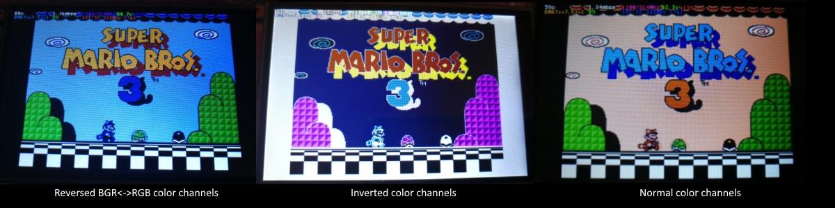
If the color channels are mixed (red is blue, blue is red, green is green) like shown on the left image, pass the CMake option -DDISPLAY_SWAP_BGR=ON to the build.
If the color intensities look wrong (white is black, black is white, color looks like a negative image) like seen in the middle image, pass the CMake option -DDISPLAY_INVERT_COLORS=ON to the build.
If the colors looks off in some other fashion, it is possible that the display is just being driven at a too high SPI bus speed, in which case try making the display run slower by choosing a higher -DSPI_BUS_CLOCK_DIVISOR= option to CMake. Especially on ILI9486 displays it has been observed that the colors on the display can become distorted if the display is run too fast beyond its maximum capability.
fbcp-ili9341 needs a few megabytes of GPU memory to function if DMA transfers are enabled. The gpu_mem boot config option dictates how much of the Pi's memory area is allocated to the GPU. By default this is 64MB, which has been observed to not leave enough memory for fbcp-ili9341 if HDMI is run at 1080p. If this error happens, try increasing GPU memory to eg 128MB by adding a line gpu_mem=128 in /boot/config.txt .
As the number of supported displays, Raspberry Pi device models, Raspbian/Retropie/Lakka OS versions, accompanied C++ compiler versions and fbcp-ili9341 build options have grown in number, there is a combinatorial explosion of all possible build modes that one can put the codebase through, so it is not easy to keep every possible combo tested all the time. Something may have regressed or gotten outdated. Stay calm, and report a bug.
You can also try looking through the commit history to find changes related to your configuration combo, to see if there's a mention of a known good commit in time that should work for your case. If you get an odd compiler error on cmake or make lines, those will usually be very easy to fix, as they are most of the time a result of some configurational oversight.
First, make sure the display is a 4-wire SPI and not a 3-wire one. A display is 4-wire SPI if it has a Data/Control (DC) GPIO line that needs connecting. Sometimes the D/C pin is labeled RS (Register Select). Support for 3-wire SPI displays does exist, but it is experimental and not nearly as well tested as 4-wire displays.
Second is the consideration about display speed. Below is a performance chart of the different displays I have tested. Note that these are sample sizes of one, I don't know how much sample variance there exists. Also I don't know if it is likely that there exists big differences between displays with same controller from different manufacturers. At least the different ILI9341 displays that I have are all quite consistent on performance, whether they are from Adafruit or WaveShare or from BuyDisplay.com.
| Fournisseur | Taille | Résolution | Contrôleur | Rated SPI Bus Speed | Obtained Bus Speed | Fréquence d'images |
|---|---|---|---|---|---|---|
| Adafruit PiTFT | 2.8" | 240x320 | ILI9341 | 10MHz | 294MHz/4=73.50MHz | 59.81 fps |
| Adafruit PiTFT | 2.2" | 240x320 | ILI9340 | 15.15MHz | 338MHz/4=84.50MHz | 68.76 fps |
| Adafruit PiTFT | 3.5" | 320x480 | HX8357D | 15.15MHz | 314MHz/6=52.33MHz | 21.29 fps |
| Adafruit OLED | 1.27" | 128x96 | SSD1351 | 20MHz | 360MHz/20=18.00MHz | 91.55 fps |
| Waveshare RPi LCD (B) IPS | 3.5" | 320x480 | ILI9486 | 15.15MHz | 255MHz/8=31.88MHz | 12.97 fps |
| maithoga TFT LCD | 3.5" | 320x480 | ILI9486L | 15.15MHz | 400MHz/8=50.00MHz | 13.56 fps* |
| BuyDisplay.com SPI TFT copy #1 | 3.2" | 240x320 | ILI9341 | 10MHz | 310MHz/4=77.50MHz | 63.07 fps |
| BuyDisplay.com SPI TFT copy #2 | 3.2" | 240x320 | ILI9341 | 10MHz | 300MHz/4=75.00MHz | 61.03 fps |
| Arduino A000096 LCD | 1.77" | 128x160 | ST7735R | 15.15MHz | 355MHz/6=59.16MHz | 180.56 fps |
| Tontec MZ61581-PI-EXT 2016.1.28 | 3.5" | 320x480 | MZ61581 | 128MHz | 280MHz/2=140.00MHz | 56.97 fps |
| Adafruit 240x240 Wide Angle TFT | 1.54" | 240x240 | ST7789 | ? | 340MHz/4=85.00MHz | 92.23 fps |
| WaveShare 240x240 Display HAT | 1.3" | 240x240 | ST7789VW | 62.5MHz | 338MHz/4=84.50MHz | 91.69 fps |
| WaveShare 128x128 Display HAT | 1.44" | 128x128 | ST7735S | 15.15MHz | (untested) | (untested) |
| KeDei v6.3 | 3.5" | 320x480 | MPI3501 | ? | 400MHz/12=33.333MHz | 4.8fps ** |
In this list, Rated SPI Bus Speed is the maximum clock speed that the display controller is rated to run at. The Obtained Bus Speed column lists the fastest SPI bus speed that was achieved in practice, and the core_freq BCM Core speed and SPI Clock Divider CDIV setting that was used to achieve that rate. Note how most display controllers can generally be driven much faster than what they are officially rated at in their spec sheets.
The Frame Rate column shows the worst case frame rate when full screen updates are being performed. This occurs for example when watching fullscreen video (that is not a flat colored cartoon). Because fbcp-ili9341 only sends over the pixels that have changed, displays such as HX8357D and ILI9486 can still be used to play many games at 60fps. Retro games work especially well.
All the ILI9341 displays work nice and super fast at ~70-80MHz. My WaveShare 3.5" 320x480 ILI9486 display runs really slow compared to its pixel resolution, ~32MHz only. See fbcp-ili9341 ported to ILI9486 WaveShare 3.5" (B) SpotPear 320x480 SPI display for a video of this display in action. Adafruit's 320x480 3.5" HX8357D PiTFTs is ~64% faster in comparison.
The ILI9486L controller based maithoga display runs a bit faster than ILI9486 WaveShare, 50MHz versus 31.88MHz, ie +56.8% bandwidth increase. However fps-wise maithoga reaches only 13.56 vs WaveShare 12.97 fps, because the bandwidth advantage is fully lost in pixel format differences: ILI9486L requires transmitting 24 bits per each pixel (R6G6B6 mode), whereas ILI9486 supports 16 bits per pixel R5G6B5 mode. This is reflected in the above chart refresh rate for the maithoga display (marked with a star).
If manufacturing variances turn out not to be high between copies, and you'd like to have a bigger 320x480 display instead of a 240x320 one, then it is recommended to avoid ILI9486, they indeed are slow.
The KeDei v6.3 display with MPI3501 controller takes the crown of being horrible, in all aspects imaginable. It is able to run at 33.33 MHz, but due to technical design limitations of the display (see #40), effective bus speed is halved, and only about 72% utilization of the remaining bus rate is achieved. DMA cannot be used, so CPU usage will be off the charts. Even though fbcp-ili9341 supports this display, level of support is expected to be poor, because the hardware design is a closed secret without open documentation publicly available from the manufacturer. Stay clear of KeDei or MPI3501 displays.
The Tontec MZ61581 controller based 320x480 3.5" display on the other hand can be driven insanely fast at up to 140MHz! These seem to be quite hard to come by though and they are expensive. Tontec seems to have gone out of business and for example the domain itontec.com from which the supplied instructions sheet asks to download original drivers from is no longer registered. I was able to find one from eBay for testing.
Search around, or ask the manufacturer of the display what the maximum SPI bus speed is for the device. This is the most important aspect to getting good frame rates, but unfortunately most web links never state the SPI speed rating, or they state it ridiculously low like in the spec sheets. Try and buy to see, or ask in some community forums from people who already have a particular display to find out what SPI bus speed it can achieve.
One might think that since Pi Zero is slower than a Pi 3, the SPI bus speed might not matter as much when running on a Pi Zero, but the effect is rather the opposite. To get good framerates on a Pi Zero, it should be paired with a display with as high SPI bus speed capability as possible. This is because the higher the SPI bus speed is, the more autonomously a DMA controller can drive it without CPU intervention. For the same reason, the interlacing technique does not (currently at least) perform well on a Pi Zero, so it is disabled there by default. ILI9341s run well on Pi Zero, ILI9486 on the other hand is quite difficult to combine with a Pi Zero.
Ultimately, it should be noted that parallel displays (DPI) are the proper method for getting fast framerates easily. SPI displays should only be preferred if display form factor is important and a desired product might only exist as SPI and not as DPI, or the number of GPIO pins that are available on the Pi is scarce that sacrificing dozens of pins to RGB data is not possible.
Hardware-wise, there are six different ways to connect displays to the Pi. Here are the pros and cons of each:
Displays are generally manufactured to utilize one specific interfacing method, with the exception that some displays have a both I²C and SPI modes that can be configured via soldering.
Fbcp-ili9341 driver is about interfacing with SPI displays. If your display utilizes some other connection mechanism, fbcp-ili9341 will not apply.
Software-wise, there are two possible alternatives to fbcp-ili9341:
The following links proved helpful when writing this:
If you would like to help push Raspberry Pi SPI display support further, there are always more things to do in the project. Here is a list of ideas and TODOs for recognized work items to contribute, roughly rated in order of increasing difficulty.
top / htop , or with a power meter off the wall and report the results.SPI_3WIRE_PROTOCOL + ALL_TASKS_SHOULD_DMA to work together, or 3) fix up SPI_3WIRE_PROTOCOL + OFFLOAD_PIXEL_COPY_TO_DMA_CPP to work together.ALL_TASKS_SHOULD_DMA mode to be always superior in performance and CPU usage so that the non- ALL_TASKS_SHOULD_DMA path can be dropped from the codebase. (probably requires the above chaining to function efficiently)This driver is licensed under the MIT License. See LICENSE.txt. In nonlegal terms, it's yours for both free and commercial projects, DIY packages, kickstarters, Etsys and Ebays, and you don't owe back a dime. Feel free to apply and derive as you wish.
If you found fbcp-ili9341 useful, it makes me happy to hear back about the projects it found a home in. If you did a build or a project where fbcp-ili9341 worked out, it'd be great to see a video or some photos or read about your experiences.
I hope you build something you enjoy!
Best way to discuss the driver is to open a GitHub issue. You may also be able to find me over at sudomod.com Discord channel.


