Basically, all gas springs can be developed using the same set of templates. The core principles are dripping air pumping and oblique air pushing. The structure of the module is as follows: the first step is to build the frame (overall size 13X6), the second step is to reverse the throttle to evacuate, and the third step is to pump the air at an angle. The building is built in three steps, the background building is built in the fourth step, and the finishing work is done in the fifth step.

Details of the construction method of the gas spring development module in "Hypoxia"
Gas springs can basically be developed using the same set of templates (low-temperature steam nozzles and high-temperature steam nozzles are not acceptable, and hydrogen nozzles are best added to a steam engine to absorb heat)
The core principle is to pump air by dripping liquid and push air at an angle. In fact, this phenomenon may occur when pouring water from an empty bottle, but I just didn't notice it.
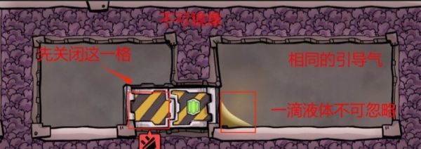
Specifically, when the structure in the figure (which can be mirrored) is formed, that is, the upper left solid, the upper right liquid, the lower left gas, and the lower right liquid, the liquid in the upper right corner will directly swap positions with the gas in the lower left corner. And this behavior has a very high priority, higher than the behavior of liquid annihilation, and there is no need to guide the gas, because it is essentially a gas-liquid transposition. (The breathable bricks in the picture are just for the liquid to look good. In fact, do not use breathable bricks)

Another mechanism is to push air at an angle, which is generally achieved by using a mechanical airlock. For example, as shown in the picture, when the mechanical airlock is opened and closed, the gas in the airlock will be squeezed into the space on the right. The conditions for this situation to be true are: there is a corresponding guide gas on the right side and it cannot be a vacuum, and there is a drop of liquid next to the door and it cannot be mirrored.
Because although the airlock is two grids in size, when it is closed, the left grid is closed first, and then the right grid is closed. When the right side is closed, the gas will be merged into the same gas on the right side first. If it cannot be merged, Disappear directly.

The structure of the module is as follows:
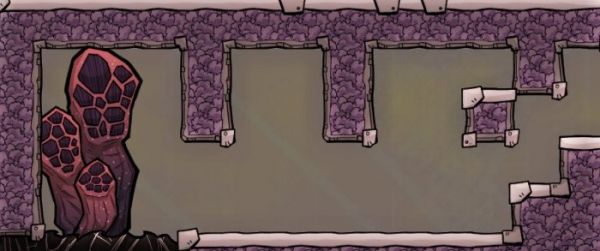
The first step is to build the frame (overall size 13X6)

The second step is to reverse the throttle and vacuum
If there is an eruption at this time, then you only need to remove the miscellaneous gas inside. Essentially, the purpose of this step is to remove the "miscellaneous gas" inside. For example, for natural gas blowholes, you only need to ensure that the gas inside is only natural gas.

Note that it is best to pour "crude oil" (it is best to use liquid naphtha for the hydrogen injection hole, but it needs to melt plastic to get it. Crude oil can also be used to absorb heat with a steam engine in time)
Then let the little person wipe the floor and wipe the locations marked in my picture until two drops of liquid are left

It should look like this after wiping it off

Then we wiped off the drop of liquid on the left and poured it into the right grid with an empty bottle (check only cleaning, crude oil, and then clean the drop of liquid that was wiped off), and finally it looked like this.

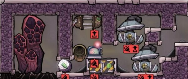
The third step is to build the building
(A brick is added on the left). The material of these buildings depends on the temperature of the gas spring you develop. If it is natural gas, you need to use steel (150℃). For chlorine gas nozzles, iron ore (60℃) will do. You can see clearly for yourself. . If it is a higher temperature spring, a steam engine must be added (more on this later).

The fourth step is to build the background building
Wire (you can also use thin wire if you want)

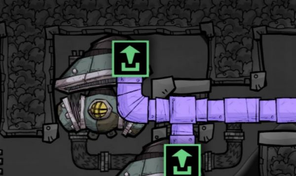
ventilation duct

Automated, the air pressure sensor is set to greater than 1000g, and a filter door is connected. The default is 5 seconds. The time sensor is connected to the mechanical airlock. Note that the red color is set to 0 first, otherwise the villain cannot come out of the card.

Water pipes are the key points here. Don’t make a mistake. Don’t connect the pipe bridge by mistake. If you connect it incorrectly, send it directly. The liquid regulating valve is set to 0.1g/s, and cannot be larger, because 100 mg of liquid will annihilate, and after the regulating valve is set, a villain needs to come over to operate it before it takes effect. It is only successful after watching the villain come over to set it.

The fifth step, finishing work
Fill the liquid pipeline with oil. Just fill it directly. After filling, the oil will stay in it for a while. It will basically be enough for you to use it for thousands of cycles without the need to replenish it.

If there is no corresponding gas inside the module at this time, then find a place to pump some, or wait for the gas spring to erupt, and wait until there is corresponding gas in the module before proceeding to the last step.
Finally, close the brick on the door and set the time sensor to green for 5 seconds and red for 5 seconds, and you're done.

If you need to add a steam engine, you can change it like this, and it is best not to use lead close to the gas spring, because the melting point of lead is 327.5°C, which is far lower than 500°C. Although the temperature of the entire module will tend to be 125°C in the end, It may be that the local temperature was too high at the beginning of the eruption.

Use diamonds as window bricks, or replace them with metal bricks (lead cannot be used). Two diamond temperature changing plates can be placed behind the gas spring (optional).
The key point is the upper part of the steam engine. Pour at least 4 tons of water into the steam room. The insulating bricks under the steam engine are best made of ceramics, because the steam engine is used for self-cooling and the gas spring may overheat if it is dormant for too long.
The key point is that the water pipes of steam engines and heat pipes cannot use lead. (Steam engines can use lead)

Spread two layers of liquid, with a layer of crude oil and a layer of water on top, 200Kg per grid, which is a total of 2 tons (spread the crude oil first and then the water). If you pour too much, it will be submerged, and if you pour too little, there is a risk of overheating.
