Purpose: The Purpose of this project is use Assembly programs which will be embedded into the Arduino C environment but also to be introduced to doing an input and an output from the Arduino board. The input will be a switch to start the program with a pull-up or pull-down resistor and the output will drive an LED blinking an SOS in Morse Code. It looks like it will be complicated, but you are given clues every step of the way. And you can use the previous lab delay function and R16 for the different delay times.
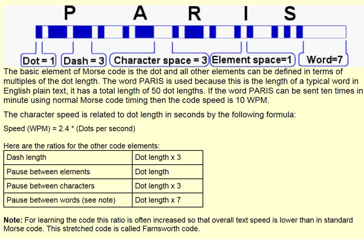
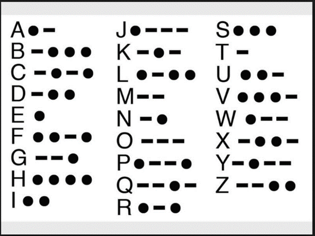
In the time of the telegram and radio telegraphy, before and even after voice was encoded, the means of communication was with a ‘tapper’ or a fancy looking switch, using Morse Code, whereby the sender could tap out a message using long and short durations or ‘taps’. On the receiving end would be a relay or a tone which would repeat the taps so one could hear it and translate it back into words. In Morse code, the letter S is encoded with 3 short dots or durations and the O is encoded with three long dashes or durations. The Morse code for mayday or help is SOS which looks like …---… …---… and so on.
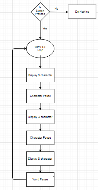
This lab will send SOS in Morse code to an LED when a switch is on and it will stop after sending the complete SOS when the switch is off.
Here is an example of what it should sound like: https://www.youtube.com/watch?v=Zsb7stKelq4
Creating an input for a switch. Such a seemingly simple operation requires some thought when doing it on a microprocessor.
Here are some general steps to make an input:
Reference the AVR datasheet section 14 about I/O ports. Note below the hardware for one I/O pin in the AVR.
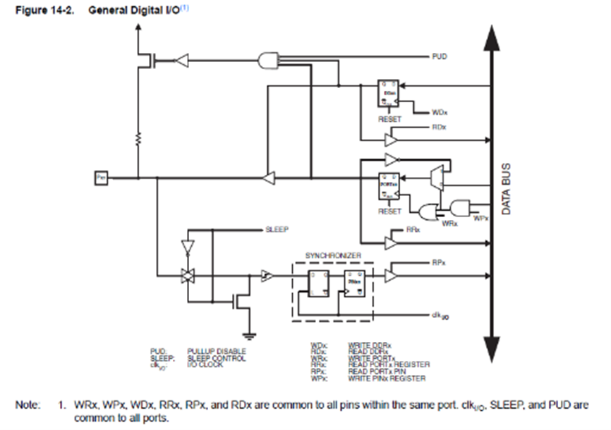
Internal hardware for an I/O pin in the AVR
All this hardware is required to be able to configure the pin as an input or an output, plus some other features like internal pullup resistors, sleep modes and synchronization with the clock. Clearly, I/O pins are not simple but we will only be concerned for this lab with a simple input or output. For this we need the DDR register and the Port for the input or output that we will be using.
Previously we saw how outputs were configured for the LED on PORTB bit 5 to blink.
You can select any port pin that is available for this on your Arduino but then you must determine its port and bit.
Output:
PORTB, register 5, bit 5, is used internally for the LED and is also brought out to a connector (pin 13 on the UNO) but do not use it externally-it does not have enough current capability to drive two LEDs.
• Suggestion: Use PORTB, register 5 bit 4 (pin 12 on the UNO) for the output
Input: There are many other choices you can use (except do not use I/O pins 0 or 1 as those are needed to communicate with the computer). • Suggestion: PORTB, register 5 bit 3 (pin 11 on the UNO) can be used as an input.
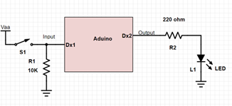
Typical setup: You choose the pins for the input and output.
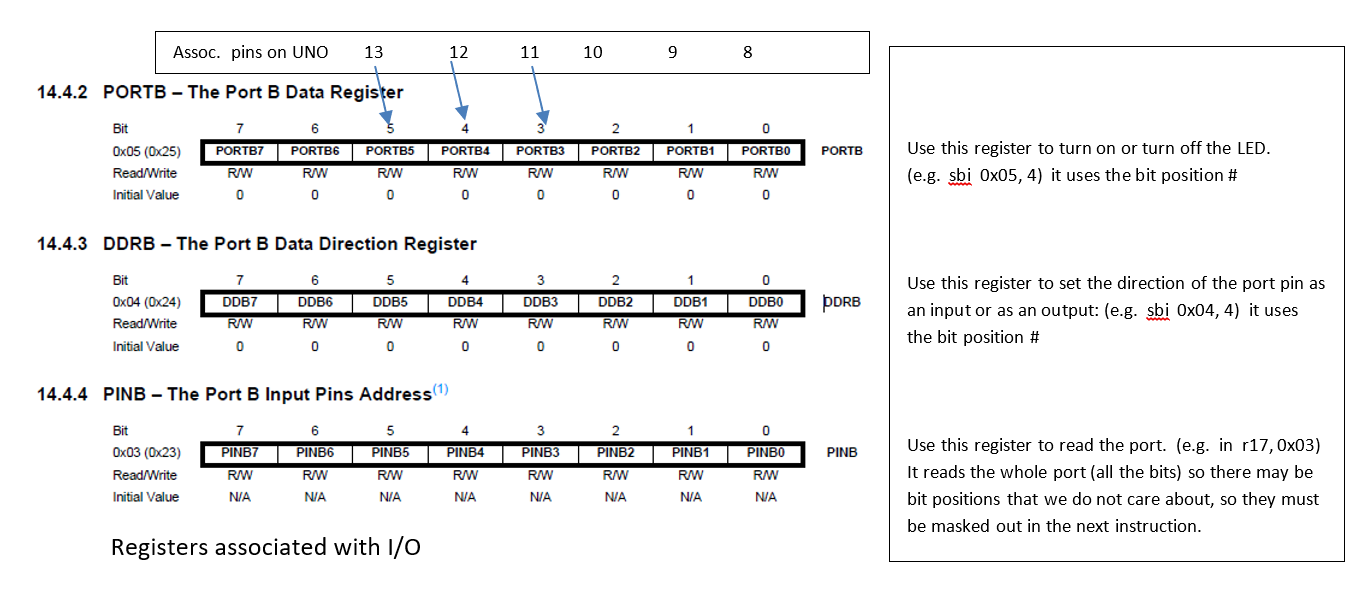
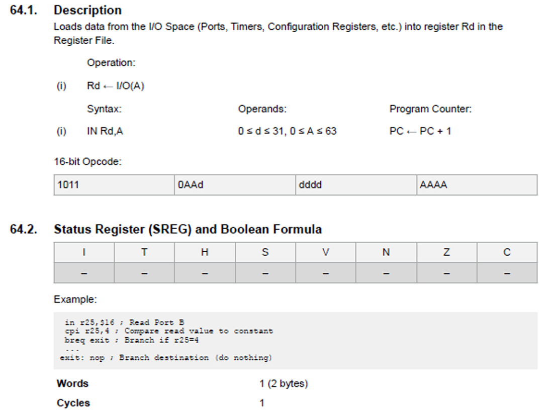
Reading an input: To read an input knowing the port, you would use the IN instruction shown below and the pins address for the port that you are using. For instance, to read the PORTB, bit 4 (pin 18 of UNO) you would use this instruction to read the port.
Loop:
IN r17, 0x03; //read PORTB pins into register 17
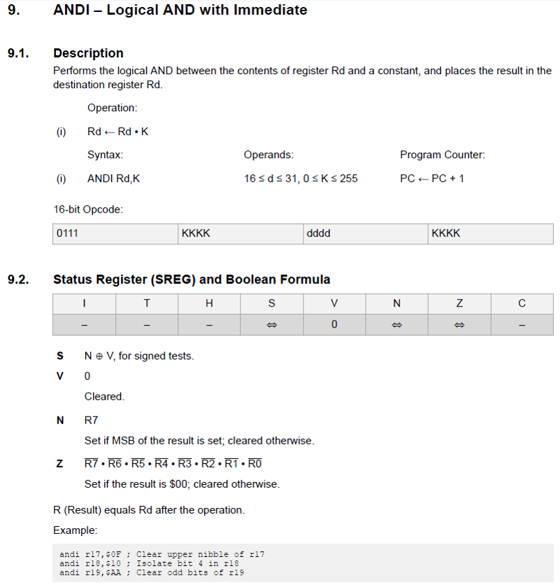
Now you need to pick out bit 4 by ANDing it with 0x10 to mask out all the other bits. After this it depends on your input configuration and whether you are using a pull-up or a pull-down. Here we are using a pulldown resistor.
If you are using a Pull-up resistor, the switch closure will result in a 0 otherwise it is a 1, so you can do the AND instruction and then branch if it is zero.
ANDI r17, 0x08; //AND r17 with 08h
BRNE start; //if the switch is not closed (i.e. 1) then go back and loop
If using a pull-down resistor the switch closure will result in a 1 otherwise it is a 0:
ANDI r17, 0x08; //AND r16 with 08h
BREQ start; //if the switch is not closed (i.e. 0) then go back and loop
Creating an output is very similar to creating an input. You have to set the port pin to be an output. Then you can use the CBI or SBI to make it a zero or a one.
Here are some general steps to make an output:
Designing the program This lab is very similar to the previous lab for the blinking LED. That sketch is attached as a base for you to start with. You just have to change the structure to create the SOS per the rules above and use an input for the switch to run the SOS and an output to drive the LED. Use the delay subroutine to setup different delays for the dots, dashes, etc. as shown below in the box.
See the document defining the timing relationships and follow these rules when designing your program for the SOS Morse Code.